Swir vision and illumination devices

Active Publication Date: 2009-09-10
L 3 COMM INSIGHT TECH
View PDF17 Cites 35 Cited by
  • Summary
  • Abstract
  • Description
  • Claims
  • Application Information

AI Technical Summary

Problems solved by technology

A drawback to these illuminators and pointers is that they can be detected by the enemy if the enemy is equipped with image intensification night vision devices, which operate from approximately 400 nm to approximately 900 nm.

Method used


Image

  • Swir vision and illumination devices
  • Swir vision and illumination devices
  • Swir vision and illumination devices

Examples


Embodiment Construction

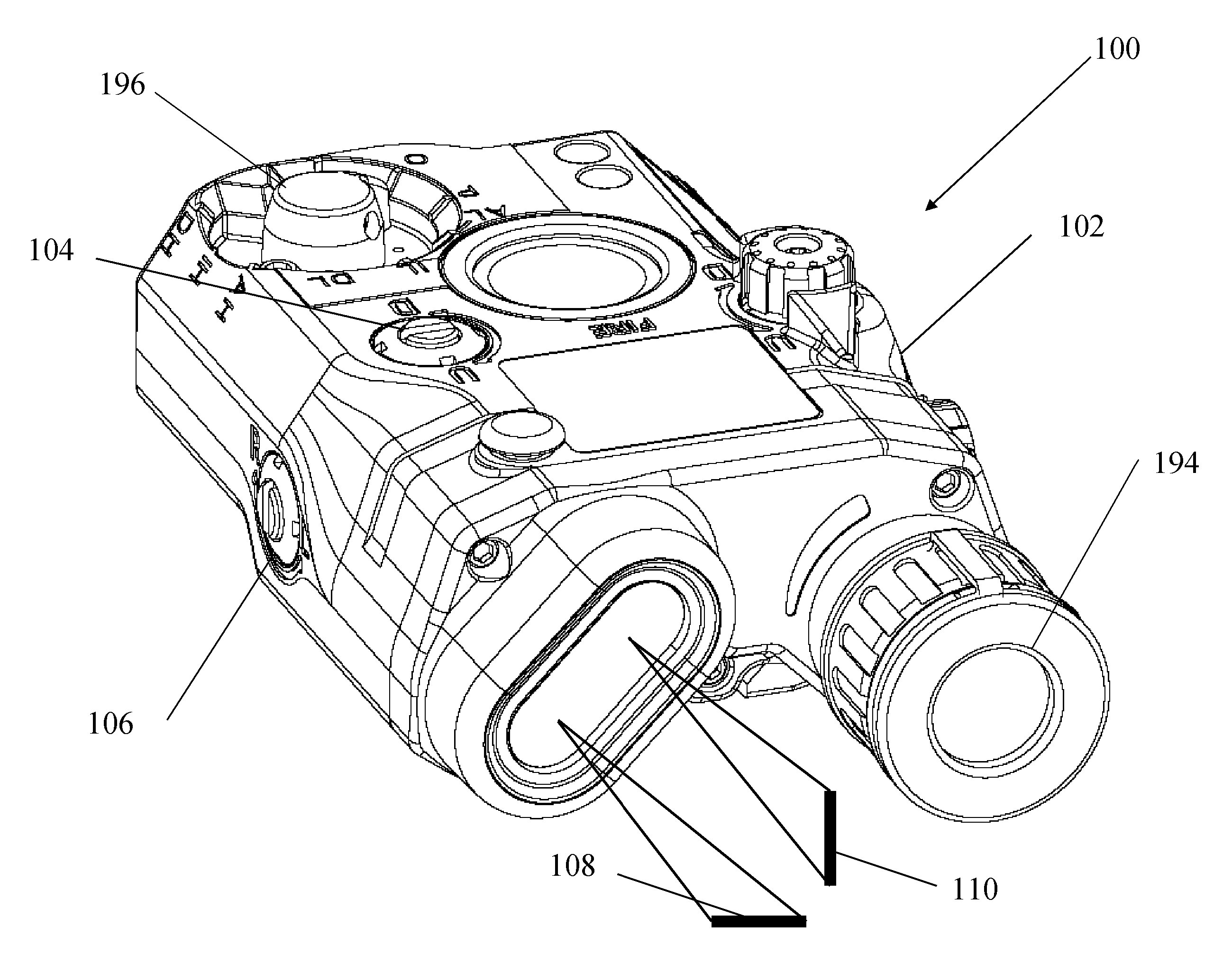
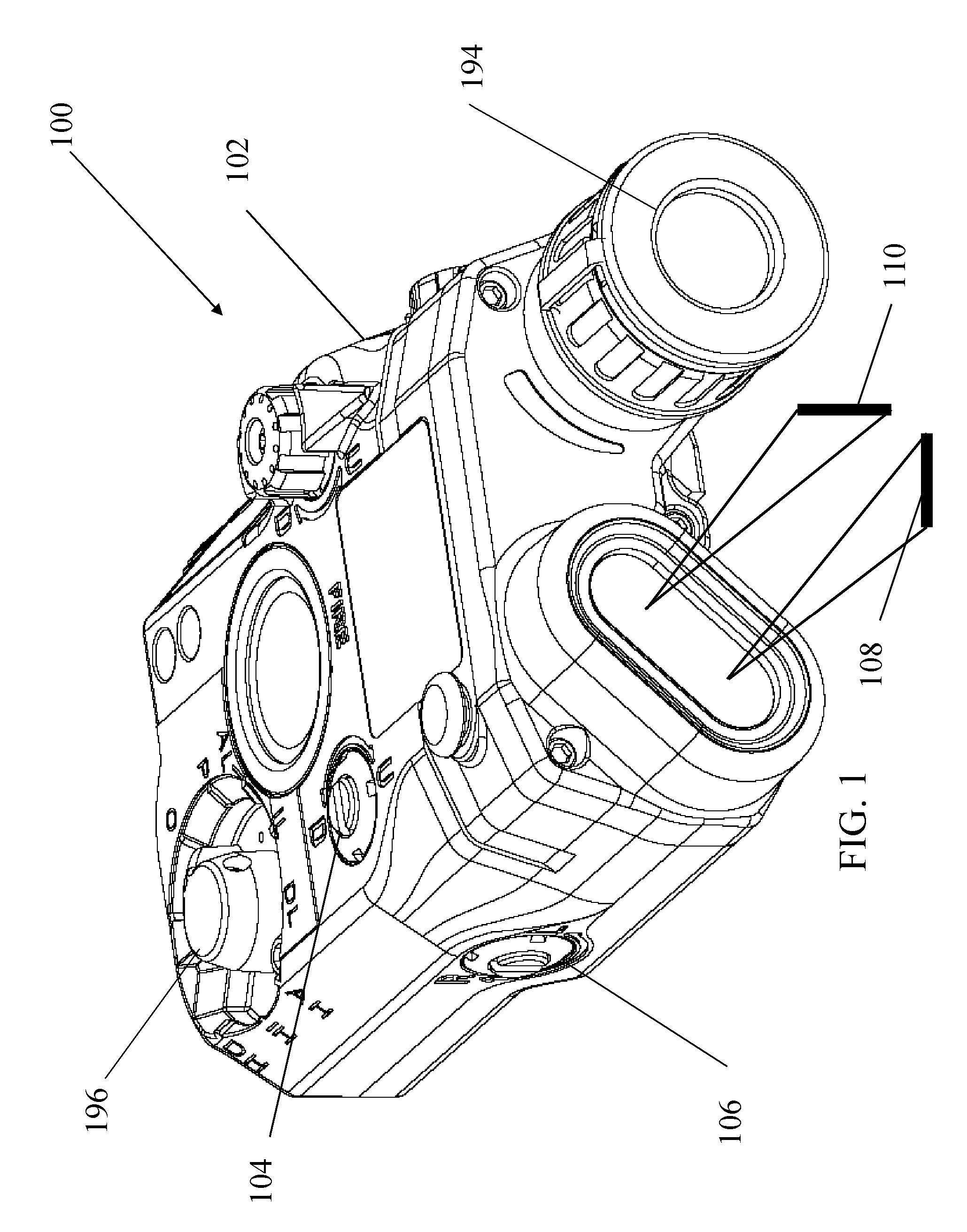
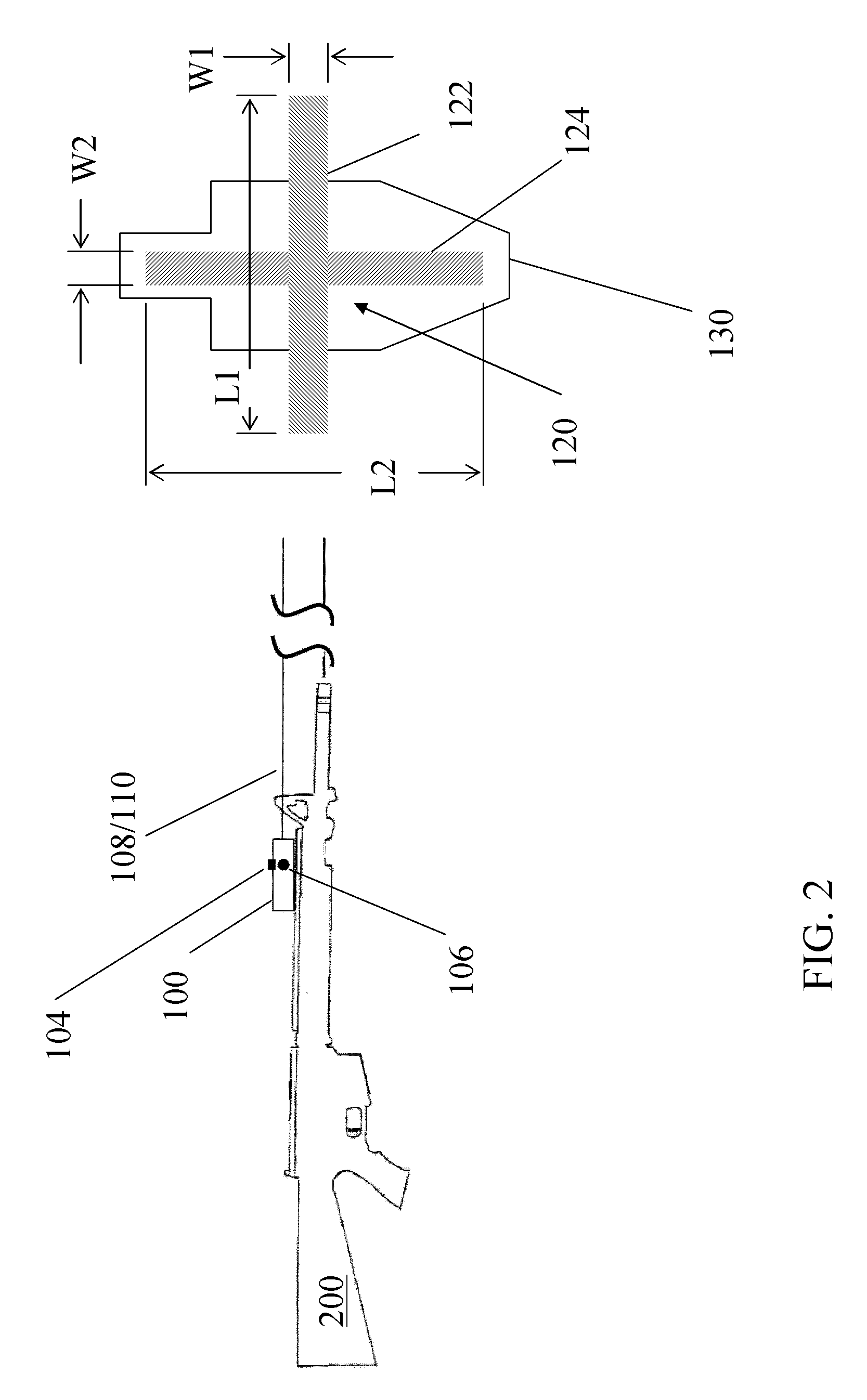
[0019]FIG. 1 is an isometric view of a weapon mountable sight 100 consistent an exemplary embodiment and FIG. 2 is a side view of the weapon mountable sight 100 attached to a weapon 200 consistent an exemplary embodiment. The sight 100 may generate a first generally rectangular light beam 108 and a second generally rectangular light beam 110 for projection of a cross 120 having a first bar 122 having a length L1 and a width W1, the length L1 being substantially greater (5× or more) than the width W1 and a second bar 124 having a length L2 and a width W2, the length L2 being substantially greater than the width W2 on a target 130. Some defocusing of the projected cross 120 may occur, but the resulting shape on a target generally conforms to a rectangle. The sight 100 may also have an infrared illuminator 194 that can be manipulated to go from a narrow beam of light to a wide, generally circular, beam of light.

[0020]The sight 100 may have a housing 102 for providing protection to inte...


PUM


Abstract

An aiming device is configured to generate an infrared cross on a target. The cross having a principal wavelength above the wavelength detectable by image intensification night vision devices. A night vision system having a short wave infrared detector includes an illuminator having a principal wavelength above the wavelength detectable by image intensification night vision devices. A beacon is configured to generate light at a wavelength above which can be scene with image intensification night vision devices.

Description

CROSS REFERENCE TO RELATED APPLICATIONS[0001]The present application claims the benefit of U.S. provisional patent applications Ser. No. 60 / 885,454, filed Jan. 18, 2007, Ser. No. 60 / 909,786, filed Apr. 3, 2007, and Ser. No. 60 / 939,377, filed May 22, 2007, the entire disclosures of which are incorporated herein by reference.BACKGROUND OF THE INVENTION[0002]Night vision systems have been used by the military and law enforcement agencies and include image intensification, thermal imaging, and fusion devices. These devices may be monoculars, binoculars, or goggles and may be hand-held, weapon mounted, or helmet mounted. Night vision systems are typically equipped with one or more image intensifier tubes to allow an operator to see visible wavelength and a small portion of infrared wavelength radiation (approximately 400 nm to approximately 900 nm). They work by collecting the tiny amounts of light that are present but may be imperceptible to our eyes and amplifying it to the point that ...

Claims


Application Information

Patent Timeline
Patent Type & Authority Applications(United States)
IPC IPC(8): H01L31/00G01J1/00
CPCF41G1/35G02B27/20G02B23/12G01J5/089G01J5/07
Inventor JANCIC, DALE A.GRAUSLYS, RICHARD P.HOHENBERGER, ROGER T.
Owner L 3 COMM INSIGHT TECH
Why Eureka
Try Eureka