
Support system for flexible pipe

a flexible pipe and support system technology, applied in the direction of pipe supports, pipe expansion compensation, pipe elements, etc., can solve the problems of affecting the installation, affecting the installation, and affecting the installation effect, so as to reduce the stress on the flexible pipe loop and joints

Inactive Publication Date: 2009-09-10
METRAFLEX
View PDF8 Cites 20 Cited by
  • Summary
  • Abstract
  • Description
  • Claims
  • Application Information

AI Technical Summary

Benefits of technology

[0004]In view of the above-described circumstances, a support system consistent with the present invention is provided for use with a flexible pipe loop installed in a non-vertical orientation in a pipe run so that the flexible pipe loop is inhibited from sagging and reducing the stress on the flexible pipe loop and joints and the effectiveness of the pipe loop to absorb movement in the pipe.

Problems solved by technology

In conventional piping installations, there is the inevitable problem of movement of pipes in the installation.
Such movement often causes the pipes to leak or break apart.
Block supports that are typically used to support flexible pipe loop elbows, such as shown in FIG. 7 of the Argersinger patent, often cannot not be employed in ceilings or walls.
Conventional hanger supports for flexible pipe loop elbows are typically connected to the apex or outermost point of each bend in the pipe loop, such as shown in FIG. 4 of the Richter patent, which causes a bending force on the flexible pipe members, particularly at the connection between the flexible pipe members and the rigid elbows, causing the flexible pipe loop members to sag downward, limiting the effectiveness of the flexible pipe loop to absorb movement.
Such sagging also adds stress to the flexible pipe loop, and places stress on the connection between the flexible pipes and the rigid elbows, thereby decreasing the stability and life of the flexible pipe loop.

Method used


Image

  • Support system for flexible pipe
  • Support system for flexible pipe
  • Support system for flexible pipe

Examples


Embodiment Construction

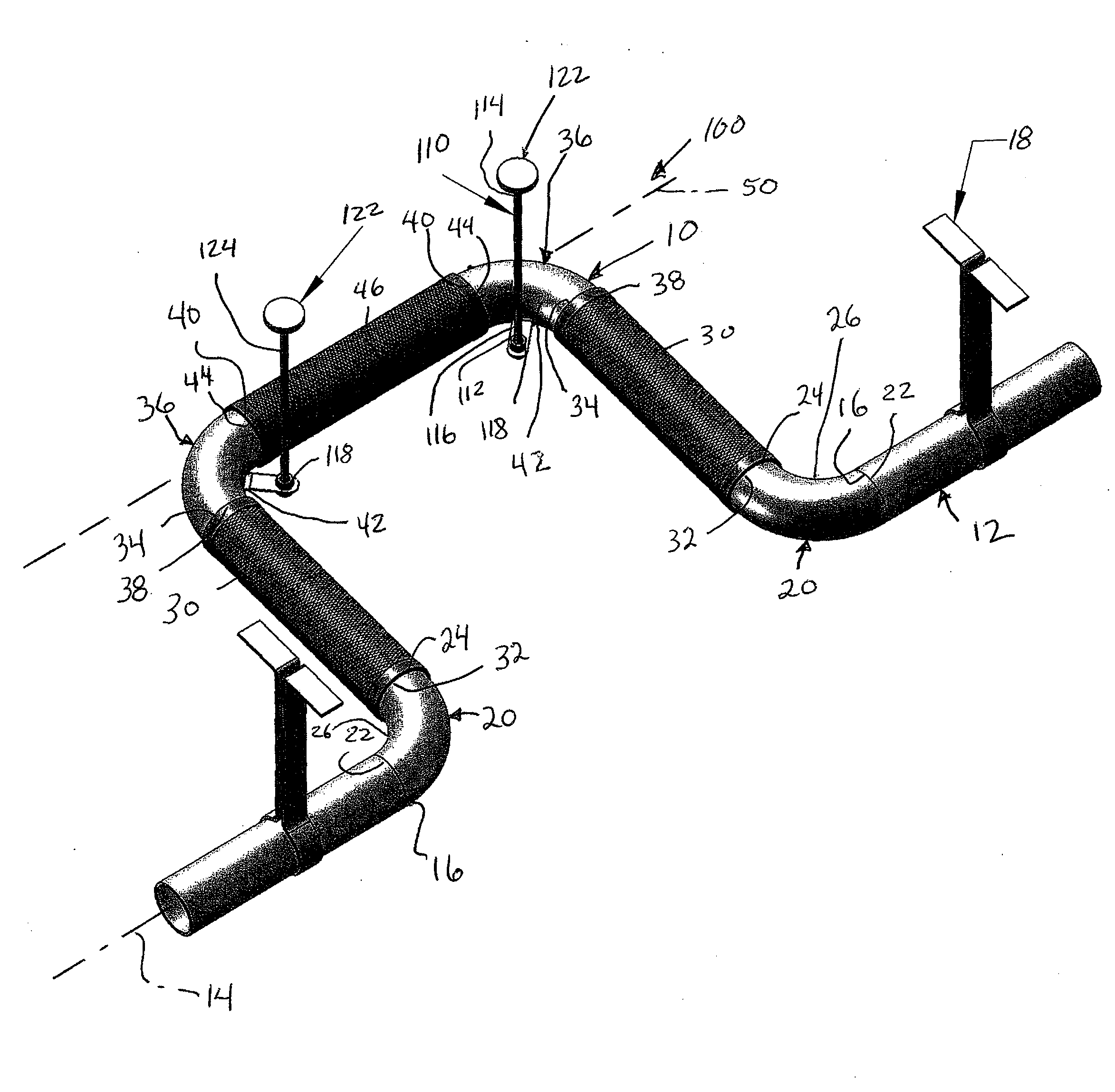
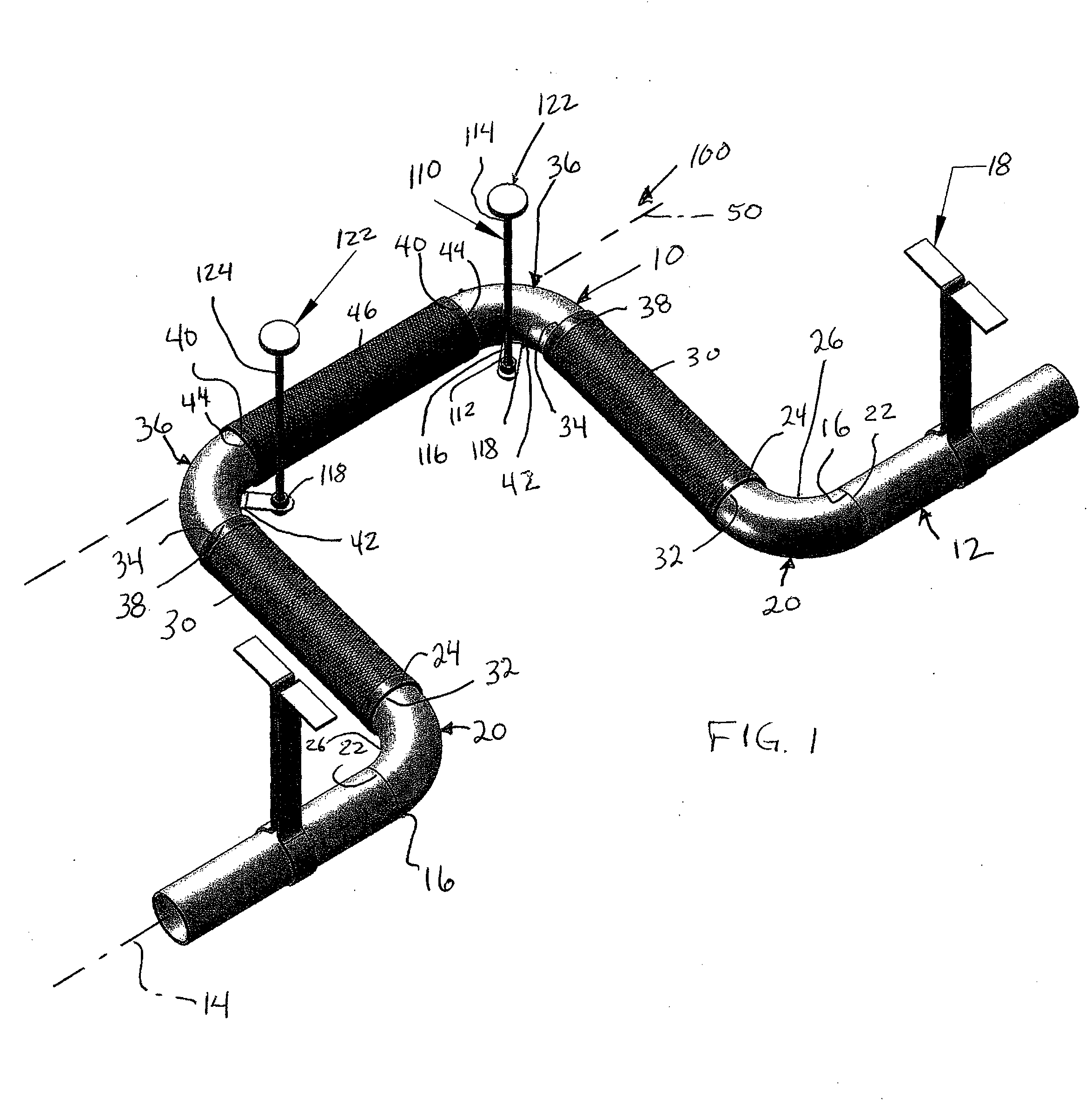
[0014]In FIG. 1, there is illustrated a support system 100 for a flexible pipe loop 10 consistent with the present invention, where the flexible pipe loop 10 is installed in a horizontal or non-vertical position in a pipe run 12 extending along a longitudinal axis 14. As discussed further below, the support system 100 inhibits the flexible pipe loop 10 from sagging when the flexible pipe loop is installed in a non-vertical orientation. The pipe run 12 is divided along its length to form a pair of open ends 16, which are attached to the pipe loop 10. The pipe run 12 may be supported by hanger supports or pipe guides 18.

[0015]As shown in FIG. 1, the pipe loop 10 comprises a pair of oppositely disposed pipe run elbows 20, each having a first open end 22 configured to mate with one of the open ends 16 of the divided pipe 12, a second open end 24, and a bend 26 (e.g., 30 degrees, 45 degrees, or as shown, 90 degrees) between the two ends 22 and 24. Other angles for the bend 26 could also ...


PUM


Abstract

A support system for a flexible pipe loop installed in a pipe run extending along a pipe run axis. The loop includes at least a pair of pipe run elbows, a pair of flexible tube members, and at least one loop elbow having first and second open ends, and an inner bend. Each pipe run elbow connects the pipe run to one end of a respective tube member. The loop elbow's inner bend is disposed towards the pipe run. The loop elbow has a centerline which is displaced away from the pipe run axis. The support system comprises a hanger rod having a first end operatively configured to attach to the loop elbow at a point which is closer to the pipe run axis than the centerline of the loop elbow at the centerline's furthest distance from the pipe run axis.

Description

BACKGROUND OF THE INVENTION:[0001]The present invention relates generally to the field of expansion pipe loops, used to compensate for and absorb movement in piping systems and more particularly to an improved support assembly for a flexible pipe loop.[0002]In conventional piping installations, there is the inevitable problem of movement of pipes in the installation. Movement of the pipes may be caused by expansion, contraction, building movement, earthquake, explosion, or other factors. Such movement often causes the pipes to leak or break apart.[0003]Flexible pipe loops have been employed to compensate for and absorb pipe movements. For example, U.S. Pat. No. 5,195,784 to Richter (1993) and U.S. Pat. No. 5,803,506 to Argersinger (1998) disclose such flexible pipe loops. While the Richter and Argersinger flexible pipe loops have gained a fair amount of acceptance in the industry, these flexible pipe loops each have one or more bends or elbows that typically require block or hanger ...

Claims


Application Information

Patent Timeline
Patent Type & Authority Applications(United States)
IPC IPC(8): F16L3/08
CPCF16L51/04F16L3/133
Inventor RICHTER, JAMES R.
Owner METRAFLEX
Features
  • Generate Ideas
  • Intellectual Property
  • Life Sciences
  • Materials
  • Tech Scout
  • Unparalleled Data Quality
  • Higher Quality Content
  • 60% Fewer Hallucinations
Learn More