Image Processing Apparatus, Image Processing Method, and Computer Program for Processing Images
- Summary
- Abstract
- Description
- Claims
- Application Information
AI Technical Summary
Benefits of technology
Problems solved by technology
Method used
Image
Examples
first embodiment
A. FIRST EMBODIMENT
[0058]A1. Configuration of Apparatus
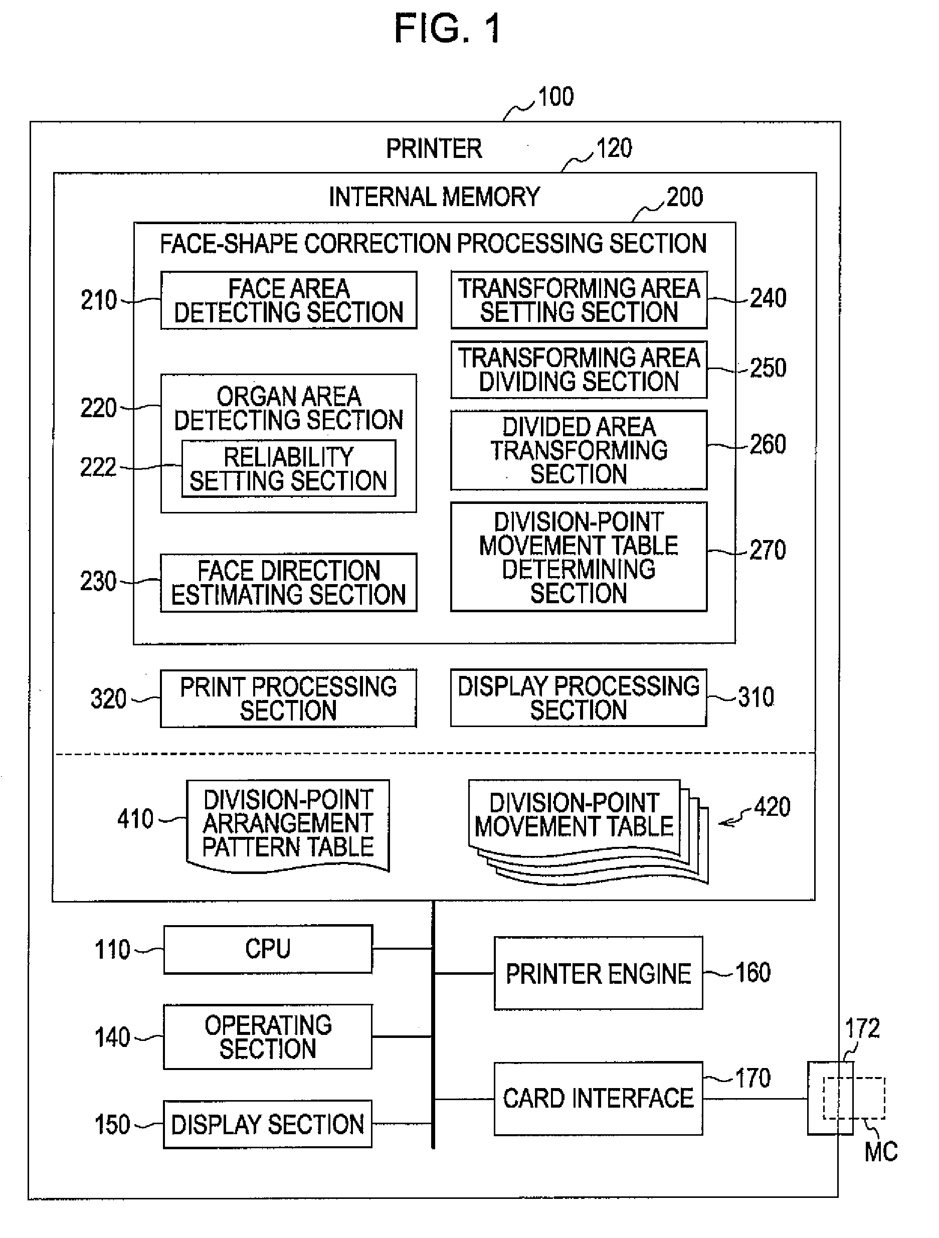
[0059]FIG. 1 is a block diagram of a printer 100 as an image processing apparatus according to a first embodiment of the invention. Printer 100 is a color ink jet printer for direct printing, in which an image is printed out on the basis of image data obtained from a memory card MC or the like. The printer 100 includes an internal memory 120, a CPU 110, an operating section 140, a display section 150, a printer engine 160, a card interface (card I / F) 170, and a card slot 172.
[0060]The internal memory 120 consists of a ROM and / or a RAM, and includes a face-shape correction processing section 200, a display processing section 310, a print processing section 320, a division-point arrangement pattern table 410, and a division-point movement table 420. The face-shape correction processing section 200 is a computer program embodied on a computer-readable medium for executing a face-shape correction process under a predetermined operat...
second embodiment
B. SECOND EMBODIMENT
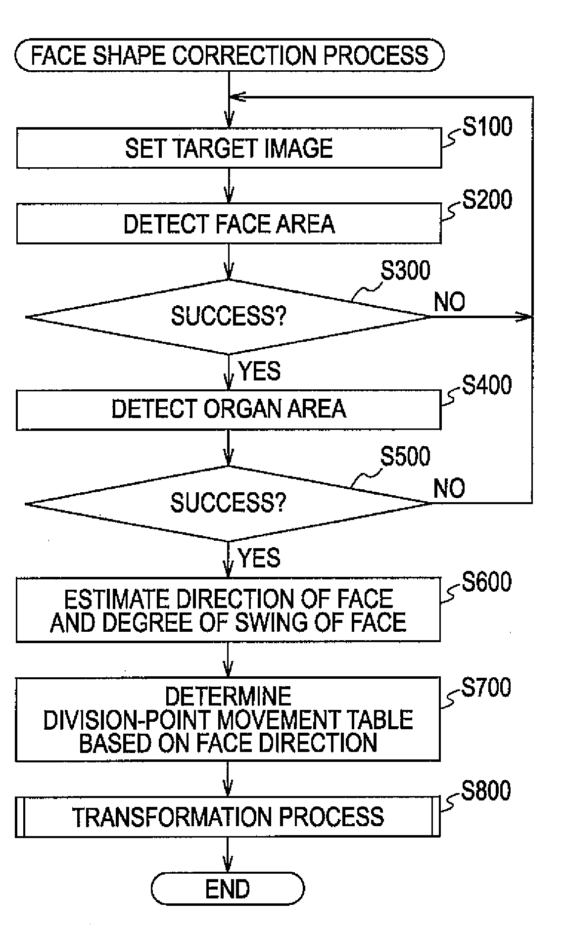
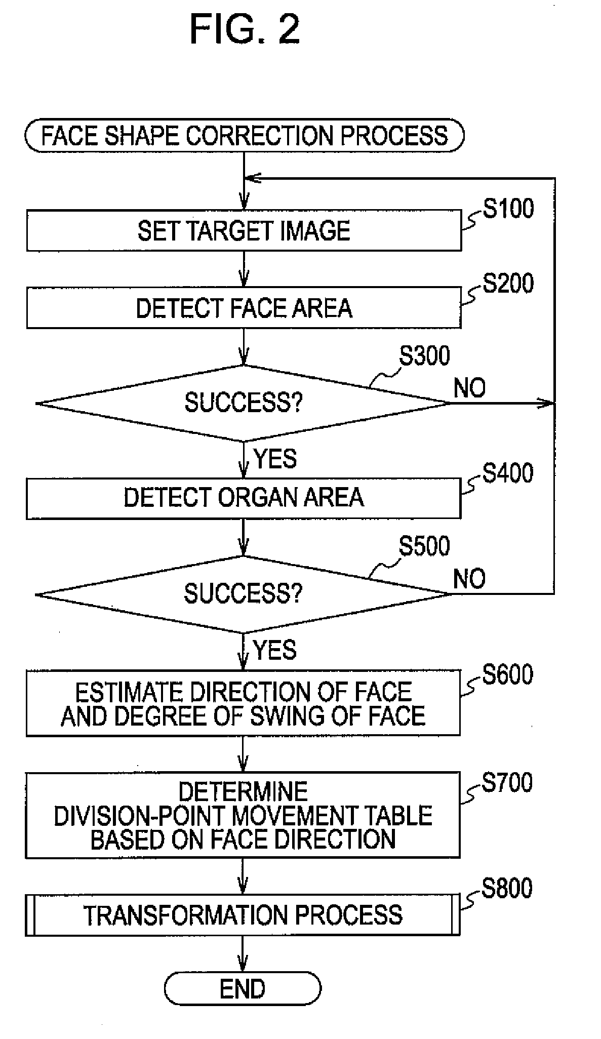
[0129]FIG. 21 is a flowchart of a face shape correction process according to a second embodiment. The process and printer in the second embodiment is different from the process and printer 100 of the first embodiment in that step S650 is added and executed between steps S600 and S700. Otherwise, the first and second embodiments are the same.
[0130]Specifically, after estimating a direction and degree of swing of a face in step S600, in step S650, the face direction estimating section 230 decides whether the degree of swing is in a range equal to or larger than −60° and equal to or smaller than +60°. When the degree of swing is in the range, steps S700 and S800 (FIG. 9) are executed. On the other hand, when the degree of swing is smaller than −60° or larger than +60°, steps S700 and S800 are not executed and the face shape correction process is terminated.
[0131]The printer of the second embodiment has a similar effect to that of the printer 100 of the first embodim...
third embodiment
C. THIRD EMBODIMENT
[0132]FIG. 22 is an explanatory diagram schematically showing movement distances of the division points D set in each table constituting the division-point movement table 420 according to a third embodiment. The upper graph in FIG. 22 has a meaning equal to that of the upper graph in FIG. 18, and the lower graph in FIG. 22 has a meaning equal to that of the lower graph in FIG. 18. Moreover, the horizontal and vertical axes in the graphs of FIG. 22 are the same as those in FIG. 18.
[0133]The movement distances of the division points D set in each table for a printer in the third embodiment are different from those for printer 100 of the first embodiment. Specifically, the movement distances of the division points D11, D21 and D12 located at the left side are constant (see FIG. 18) in the first embodiment when the face is swung in the left direction, but the movement distances (relative movement distances) decrease in the third embodiment as a degree of swing of the ...
PUM
 Abstract
Description
Claims
Application Information
 - R&D
- Intellectual Property
- Life Sciences
- Materials
- Tech Scout
- Unparalleled Data Quality
- Higher Quality Content
- 60% Fewer Hallucinations
Browse by: Latest US Patents, China's latest patents, Technical Efficacy Thesaurus, Application Domain, Technology Topic, Popular Technical Reports.
© 2025 PatSnap. All rights reserved.Legal|Privacy policy|Modern Slavery Act Transparency Statement|Sitemap|About US| Contact US: help@patsnap.com


