
Electrode Array for Even Neural Pressure

a neural pressure and electrode array technology, applied in the field of neural stimulation, can solve problems such as damage to neural tissue by too much pressure, and achieve the effect of improving conta

Active Publication Date: 2009-09-10
CORTIGENT INC
View PDF8 Cites 32 Cited by
  • Summary
  • Abstract
  • Description
  • Claims
  • Application Information

AI Technical Summary

Benefits of technology

[0021]An electrode array attached to neural tissue, such as the retina, necessarily has graded pressure exerted on the tissue, with higher pressure near the attachment point. Pressure improves contact between the electrodes and neural tissue while too much pressure may damage neural tissue. Hence it is advantageous to obtain equal pressure across the array field. In the present invention multiple and selective attachment points are provided on an electrode array allowing a surgeon to select the attachment points providing the best electrode tissue contact.

Problems solved by technology

Pressure improves contact between the electrodes and neural tissue while too much pressure may damage neural tissue.

Method used


Image

  • Electrode Array for Even Neural Pressure
  • Electrode Array for Even Neural Pressure
  • Electrode Array for Even Neural Pressure

Examples


Embodiment Construction

[0041]The following description is of the best mode presently contemplated for carrying out the invention. This description is not to be taken in a limiting sense, but is made merely for the purpose of describing the general principles of the invention. The scope of the invention should be determined with reference to the claims.

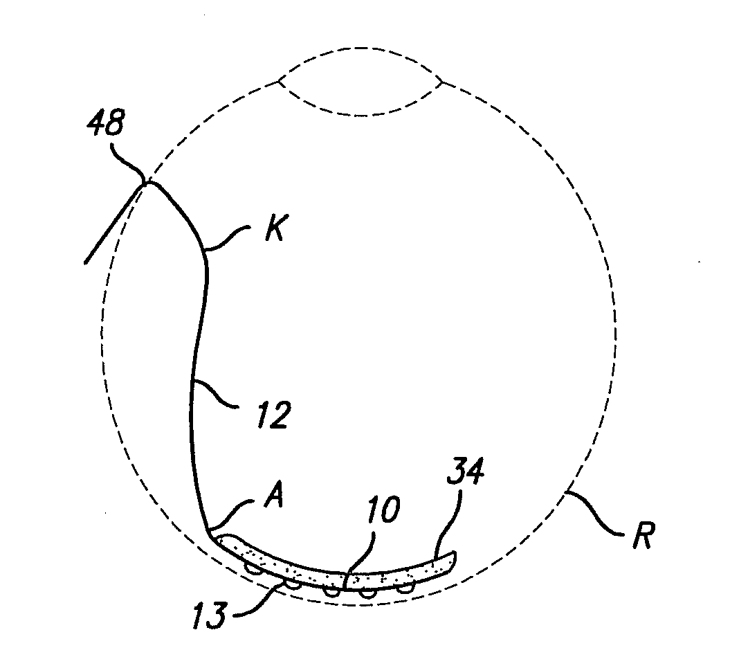
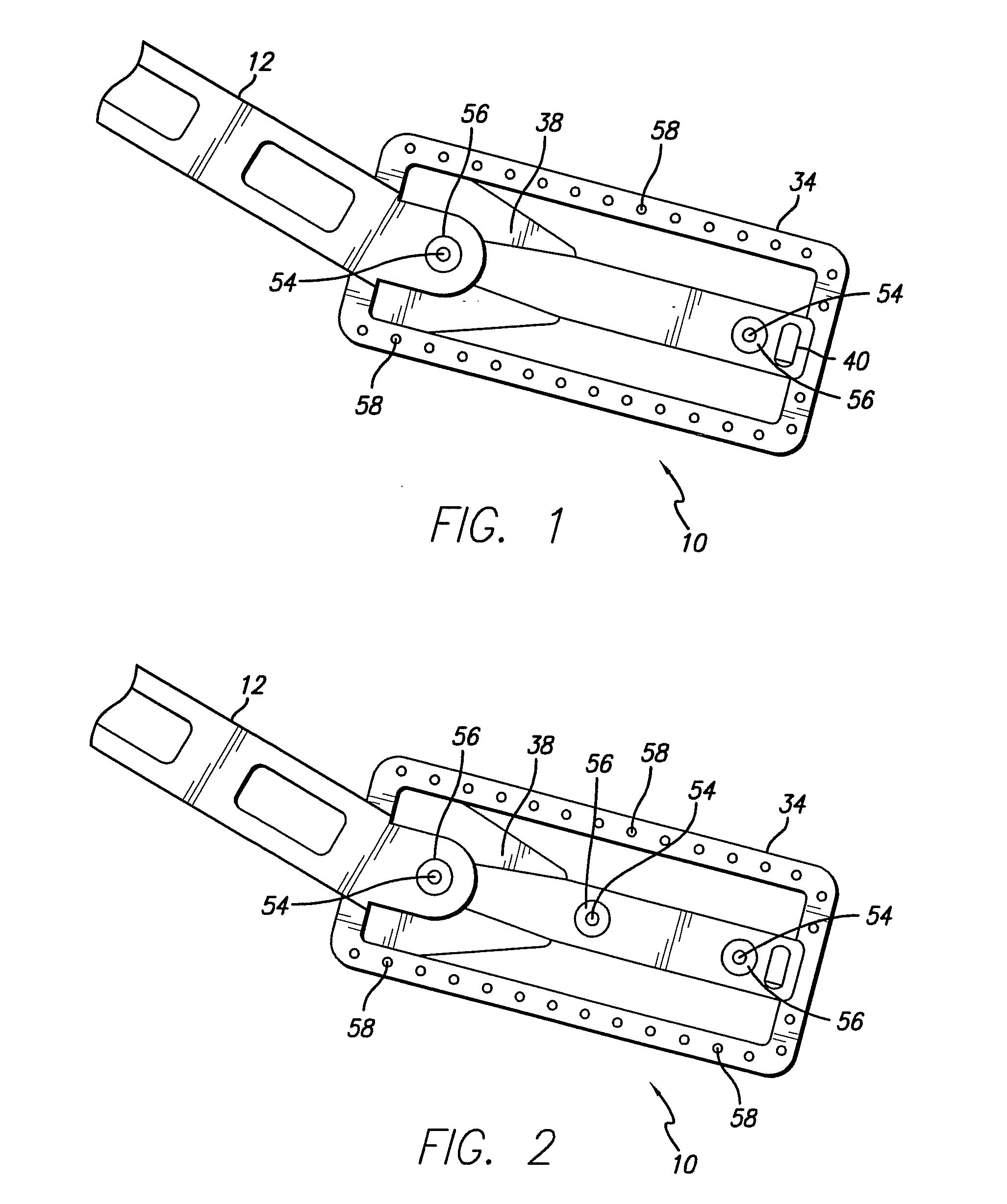
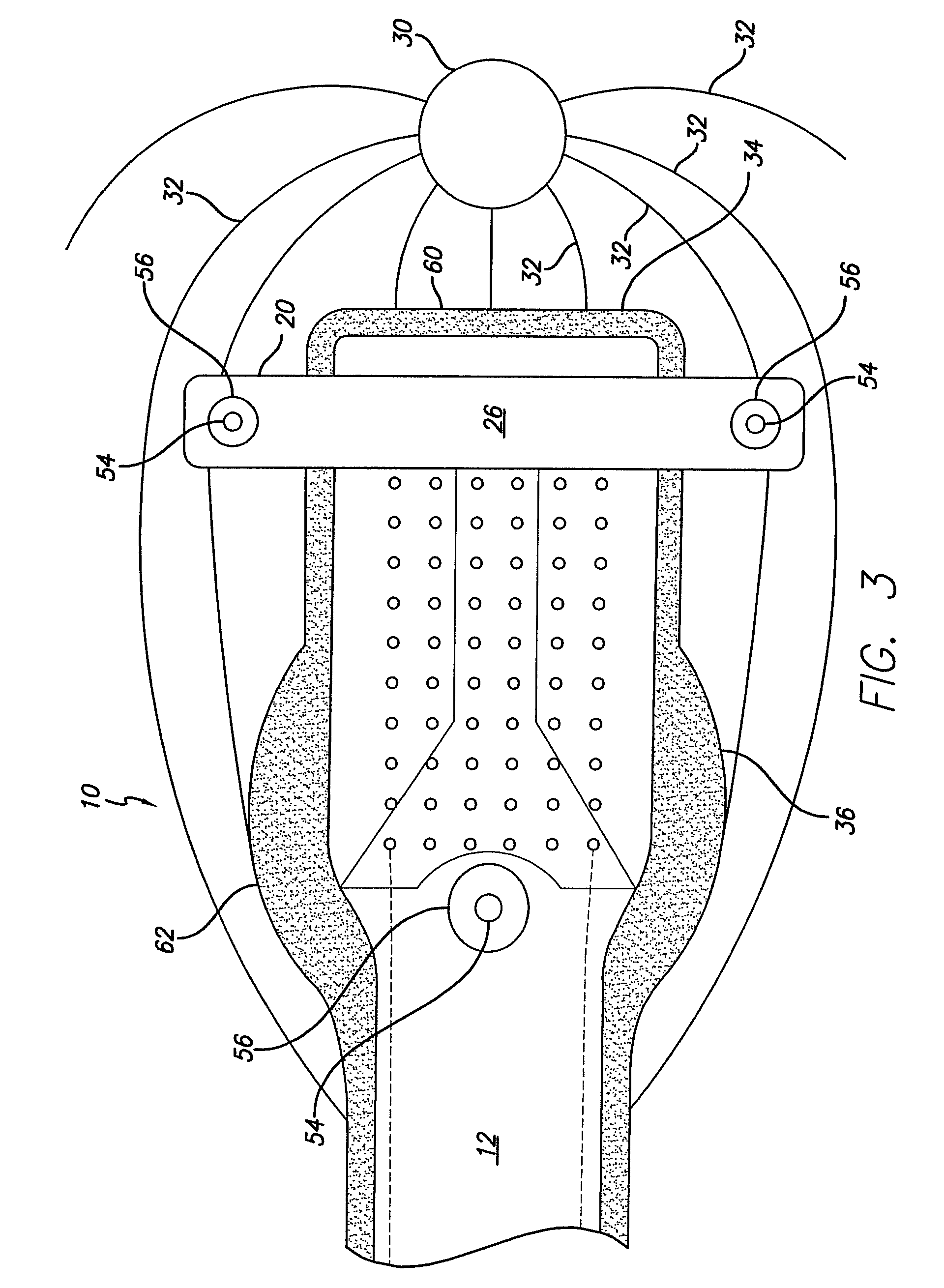
[0042]FIG. 1 shows the preferred electrode array. The array 10 is preferably made of metal traces sandwiched between polyimide layers. The array 10 and cable 12 are a single polyimide structure. A relatively hard polymer, such as polyimide, is needed to protect delicate metal traces from breaking. A molded array body 34, preferably silicone, is molded over the polyimide structure. Perforations 58 in the polyimide promote adhesion of the molded array body 34. A backbone structure 38 is molded in silicone across the back of the array 10. Attachment points 54 are provided on either side of the array field to provide even pressure across the array surface. A str...


PUM


Abstract

An electrode array attached to neural tissue, such as the retina, necessarily has graded pressure exerted on the tissue, with higher pressure near the attachment point. Greater pressure improves contact between the electrodes and neural tissue while too much pressure may damage neural tissue. Hence it is advantageous to obtain equal pressure across the array field. In the present invention multiple and selective attachment points are provided on an electrode array allowing a surgeon to select the attachment points providing the best electrode tissue contact.

Description

CROSS-REFERENCE TO RELATED APPLICATIONS[0001]This application is a continuation-in-part of U.S. application Ser. No. 12 / 258,296, filed Oct. 24, 2008 for Electrode Array for Even Neural Pressure. This application further claims the benefit of U.S. Provisional Application No. 61 / 033,723, “Attachment Arrangement for a Neural Stimulation Electrode Array”, filed Mar. 4, 2008. This application is related to and incorporates by reference US patent applications 20030069603 for “Medical Tack with a Variable Effective Length”; 20080288037 for “Flexible Circuit Electrode Array”; and 20020111658, for “Implantable retinal electrode array configuration for minimal retinal damage and method of reducing retinal stress”GOVERNMENT RIGHTS NOTICE[0002]This invention was made with government support under grant No. R24EY12893-01, awarded by the National Institutes of Health. The government has certain rights in the invention.FIELD OF THE INVENTION[0003]The present invention is generally directed to neur...

Claims


Application Information

Patent Timeline
IPC IPC(8): A61N1/05
CPCA61N1/0558A61N1/0543
Inventor GREENBERG, ROBERT J.HUMAYUN, MARK S.LITTLE, JAMES SINGLETONNEYSMITH, JORDAN MATTHEW
Owner CORTIGENT INC
Learn More