Tibial Prosthesis

a technology for tibia and tibia, applied in the field of tibial prosthesis, can solve the problems of increasing the time required for recovery and rehabilitation, increasing the surgical trauma of patients, and failure of the prosthetic implant, so as to facilitate the containment of bone cement, facilitate the preservation of bone integrity, and reduce surgical trauma

Inactive Publication Date: 2009-09-10
MAXX ORTHOPEDICS INC
View PDF40 Cites 37 Cited by
  • Summary
  • Abstract
  • Description
  • Claims
  • Application Information

AI Technical Summary

Benefits of technology

[0025]The present devices do not require that a through hole be provided for inserting a bone screw through the device into a tibia bone. In one embodiment, the present device includes no through hole, that is, the device is free of a through hole, for inserting a bone screw through the device into a tibia bone. This feature of the present devices facilitates maintaining the integrity of the bone remaining after the device is implanted, and reduces surgical trauma.
[0026]In some embodiments of the invention, the distal region includes a distally extending sidewall at least partially or even substantially entirely circumscribing the support region. A recess at least partially or even substantially entirely circumscribing the support region, for example, inside of the peripheral sidewall and / or distally extending sidewall, may be present. The recess may comprise a groove which at least partially or even substantially entirely circumscribes the support region. The peripheral sidewall / distally extending sidewall and recess provide structure effective to at least facilitate containment of bone cement used to secure the implant device to the resurfaced tibia bone, as well as prevent undesirable leakage of bone cement into the joint space.
[0027]In one advantageous aspect of the invention, one or both of the peripheral sidewall and the distally extending sidewall, for example, the distally extending sidewall, includes a flow control structure effective in controlling the flow of bone cement from the distal region. Such flow control structure is effective in enhancing the fixation of the present prosthesis device to the bone, for example, relative to an identical prosthesis device without the flow control structure. For example, the device may be structured to control flow of bone cement, that is to allow a limited or controlled flow of bone cement, for example, from the distal region, as discussed elsewhere herein, as well as prevent undesirable extrusion of bone cement exterior to the device, for example, into the joint space, after implantation of the device. The flow control structure, for example and without limitation, may include one or more notches and / or one or more sidewall grooves and / or one or more flow control ports into which the bone cement, for example, a limited or controlled amount of the bone cement, may enter to form an improved or enhanced bond, such as an improved or enhanced cement bond, between the bone, for example, the resurfaced region of the tibia bone, and the device.

Problems solved by technology

Such substantial removal of bone can cause increased surgical trauma to a patient and may increase time required for recovery and rehabilitation.
In addition, excessive removal of bone tissue may lead to failure of the prosthetic implant due to subsidence thereof into the underlying bone tissue.
Unfortunately, this often necessitates additional surgery, for example, revision surgery, in order to replace the failed implant.
Misalignment of components may occur when too much or too little bone cement is placed on the implant and the implant positioned on the bone surface.
Alternatively, if too little bone cement is used, the inadequate amounts of bone cement may result in inadequate fixation of the implant to the bone, resulting in the loosening of the implant, necessitating revision surgery to correct.
In spite of such structure, the Caspari et al devices tend to have problems, for example, with cement leakage, too much or too little cement being injected, uneven distribution of the cement, which can cause discomfort and / or other harm to the patient and / or revision surgery.

Method used


Image

  • Tibial Prosthesis
  • Tibial Prosthesis
  • Tibial Prosthesis

Examples


Embodiment Construction

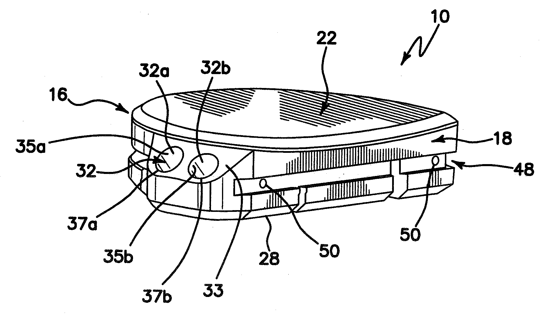
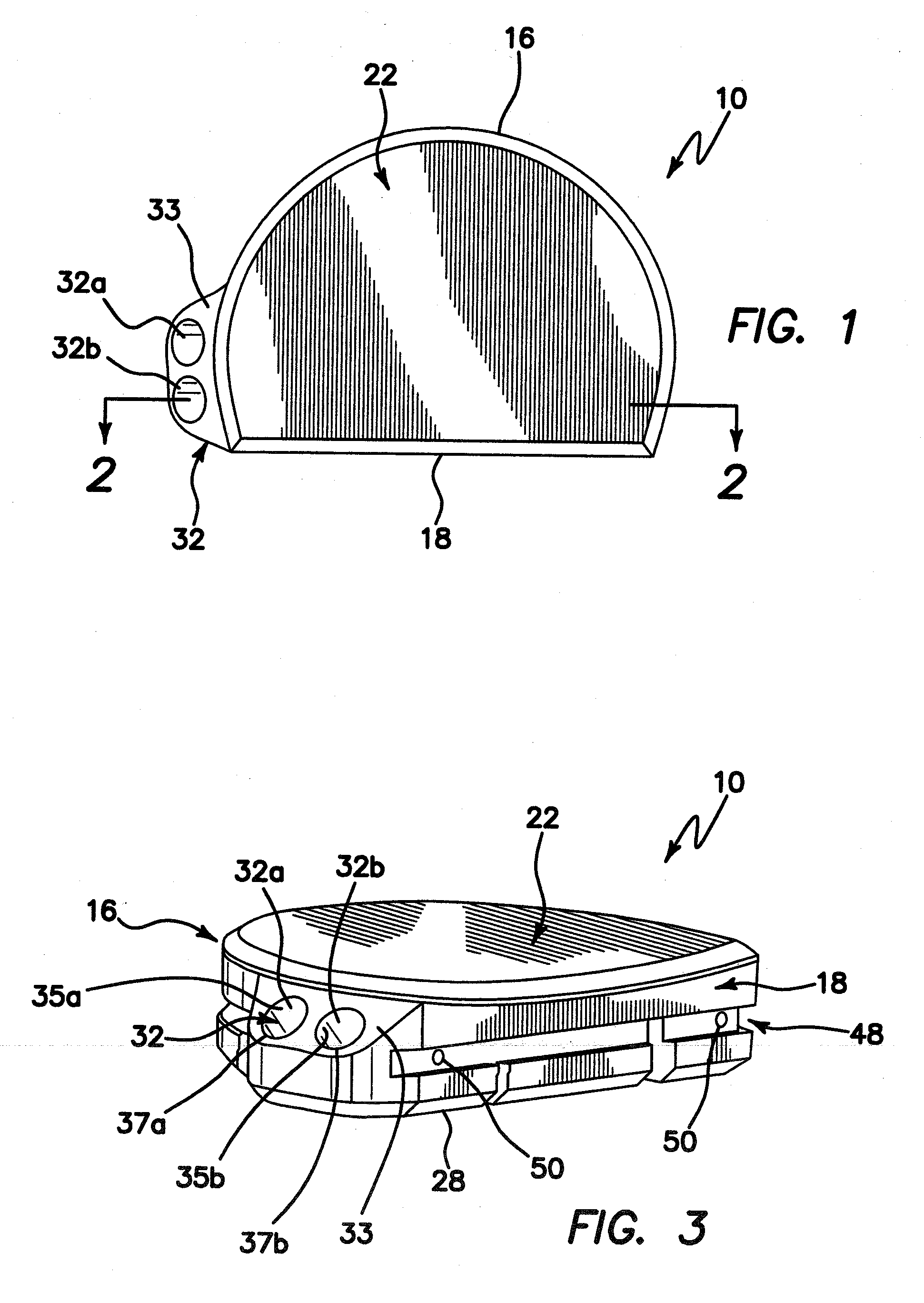
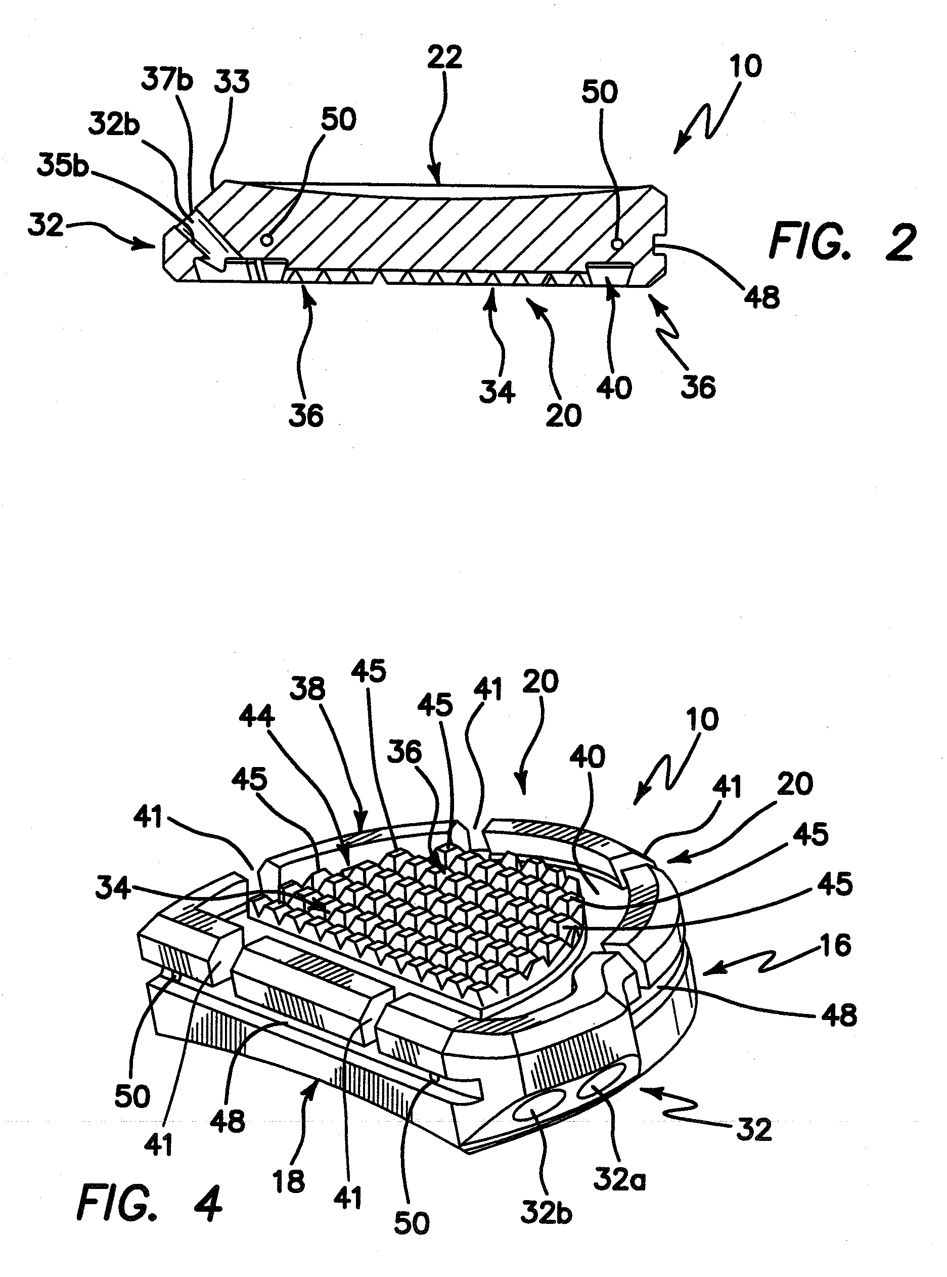
[0036]Turning now to the drawings, an exemplary embodiment of a tibial prosthesis device in accordance with the invention is shown generally at 10. The device 10 includes a curved peripheral wall or sidewall 16 and a generally straight peripheral wall or sidewall 18, which together form, in cross-section, a generally semi-circular shape, or a generally D-shape, which approximates a resurfaced area of a bone, for example, a resurfaced area of a tibia bone, on or into which the device is to be implanted.

[0037]Resurfacing of the tibia bone in preparation for implantation of tibial prosthesis device 10 may be performed using conventional techniques, for example conventional, open surgical techniques. In one embodiment, such preparation may be performed using the arthroscopic surgical devices and methods described in the co-pending U.S. provisional patent application Ser. No. 61 / 067,741, filed Feb. 29, 2008, entitled INSTRUMENTS AND METHOD FOR ARTHROSCOPY OF THE KNEE and commonly owned h...


PUM


Abstract

The present invention relates to a tibial prosthesis useful in knee replacement surgeries. The prosthesis includes one or more cement introduction ports which may be used to deliver and control delivery of bone cement to a prosthesis-bone interface after the prosthesis has been positioned on a resurfaced area of a tibia bone. The prosthesis is suitable for implantation using arthroscopic as well as open surgical procedures. The prosthesis may be used as a unicondylar implant in either compartment of the knee or in both compartments of the knee.

Description

[0001]This application claims the benefit of U.S. Provisional Application Ser. No. 61 / 067,740 filed Feb. 29, 2008; U.S. Provisional Application Ser. No. 61 / 067,741 filed Feb. 29, 2008; and U.S. Provisional Application Ser. No. 61 / 067,742 filed Feb. 29, 2008, the entire disclosure of each of which is incorporated herein by this specific reference.[0002]The present invention generally relates to prosthetic implants and, more particularly, to tibial prostheses for human knee joints.BACKGROUND OF THE INVENTION[0003]It has become a common practice to implant medical prostheses to resurfaced articular surfaces of knees, for example, during knee replacement surgery. Many of the prior art prosthetic implants require large incisions to provide adequate access to the joint space to accommodate the implant as well as the surgical tools required during the surgery. In addition, conventional knee replacement procedures often involve resection or removal of substantial amount of bone or cartilage...

Claims


Application Information

Patent Timeline
Patent Type & Authority Applications(United States)
IPC IPC(8): A61F2/38
CPCA61F2/389A61F2002/30449A61F2310/00353A61F2220/005A61F2002/3895
Inventor CLARK, RONBLAKEMORE, DAVIDMACK, ROSS
Owner MAXX ORTHOPEDICS INC
Why Eureka
Try Eureka