Orthopedic expandable devices

a technology of expandable devices and orthopedic expansion, which is applied in the field of medical devices, can solve the problems of multiple sizes (inventory), difficulty in insertion, and difficulty in construction, and achieve the effects of preventing seizure, facilitating control by users, and mechanical

Active Publication Date: 2016-10-11
CORELINK
View PDF15 Cites 44 Cited by
  • Summary
  • Abstract
  • Description
  • Claims
  • Application Information

AI Technical Summary

Benefits of technology

[0009]In one embodiment of the invention, the expandable bone device is positioned between two vertebrae, serving as a substitute for an intervertebral disc, such as in a fusion procedure. The expandable bone device acts as a spacer that enhances the fusion construction stability and promotes anterior bone column continuity when fusion occurs. The device is introduced through a small portal of entry (minimally invasive), which reduces surgical trauma and minimizes the inventory needed to cover all sizes and levels. Once located, the device is expanded in height to an optimal fit in the disc space.
[0017]In one embodiment of the invention, the expandable bone device can be a positive, self-locking expandable bone device. For example, after expansion to the required height, the device can be locked in place by a ratchet mechanism. The ratchet structure may be attached to the walls of the elements, and produces a positive lock at the desired height. The ratchet structure provides small increments in height, which are easily controlled by the user.
[0018]In one embodiment of the invention, mechanical seizure may be avoided by enclosing the moving parts so they smoothly glide in a fixed niche case. Additionally or alternatively, one or more guides can be used to guide the movement of the parts and prevent seizure. If a ratchet is used with a guide, the inner free end of the guide or some other tool can be used to release the ratchet, e.g., by pushing the ratchet outwards or inwards, so as to disengage the ratchet and allow the device to collapse down to its initial position, or by elastically deforming the wall to which the ratchet is engaged, thereby freeing the ratchet from the wall. If a ratchet is used, a transverse beam may be added between free ends of the internal wall of the device to avoid collapse of the center of the device which could cause disengagement of the ratchet.

Problems solved by technology

However, all existing devices have certain drawbacks, such as difficulty of construction, insertion, bulkiness, inadequate surface coverage in area and / or height, multiple sizes (inventory) and others.

Method used


Image

  • Orthopedic expandable devices
  • Orthopedic expandable devices
  • Orthopedic expandable devices

Examples


Embodiment Construction

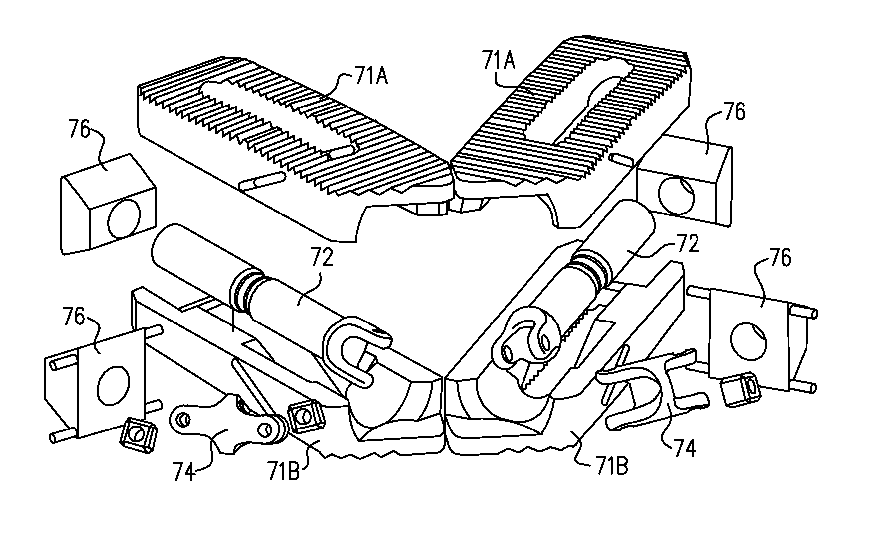
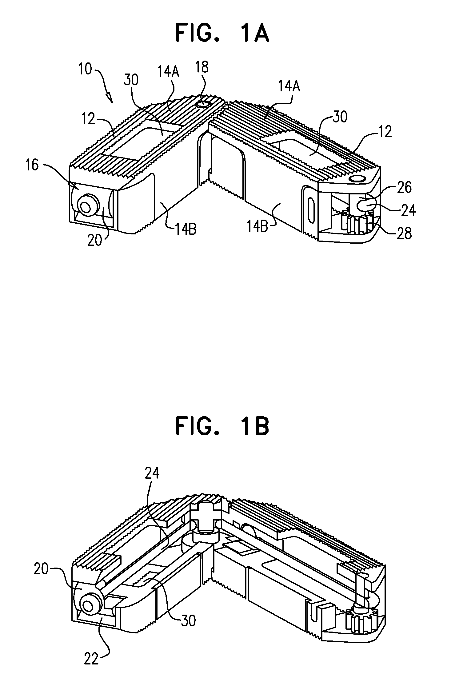
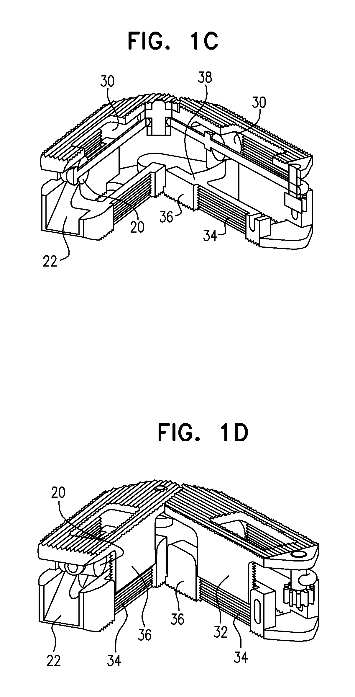
[0030]Reference is now made to FIGS. 1A-1D, which illustrate an expandable bone device 10, constructed and operative in accordance with an embodiment of the invention, in a contracted orientation (FIGS. 1A-1B) and an expanded orientation (FIGS. 1C and 1D).

[0031]Expandable bone device 10 includes a plurality of linking elements 12, each of which includes upper and lower support plates 14A and 14B, which in this embodiment, may be expanded by an intermediate wedge mechanism 16, as is described further below. Adjacent linking elements 12 are pivotally connected to one another with hinges 18.

[0032]In one embodiment, the wedging mechanism 16 includes a block 20 of any suitable size and shape, arranged to slide on a ramp 22 formed in one of the linking elements 12. Block 20 is connected to a wire or other slender element 24, which wraps around hinge 18 and is wound on an axle 26 of a gear drive 28. Gear drive 28 is rotatable by a suitable actuator (not shown), such as a gear motor. By sui...


PUM


Abstract

An expandable bone device that includes a plurality of linking elements pivotally connected to one another about a hinge, wherein each of the linking elements has upper and lower support plates. An expansion mechanism is operatively connected to the linking elements and can move the upper support plate closer or further with respect to the lower support plate.

Description

CROSS-REFERENCE TO OTHER APPLICATIONS[0001]This application claims priority from U.S. Provisional Patent Application 61 / 786,655, filed Mar. 15, 2013.FIELD OF THE INVENTION[0002]The present invention relates generally to medical devices, and, more particularly, to implantable devices used to strengthen or support bony structures in the body, such as but not limited to, intervertebral or intravertebral devices to stabilize the human spine.BACKGROUND OF THE INVENTION[0003]Implant devices, such as vertebral spacers, intravertebral or intervertebral fusion devices and disc replacement devices, have been developed to assist with stabilization and fixation or functional support of the spine. Examples include pre-assembled rings, cages, boxes, dowels, and wedges of varying size and construction, such as meshes or plates, movable disc surfaces, gel or polymer spacers, elastomers and structures. However, all existing devices have certain drawbacks, such as difficulty of construction, insertio...

Claims


Application Information

Patent Timeline
Patent Type & Authority Patents(United States)
IPC IPC(8): A61F2/44A61F2/46A61F2/28A61F2/30
CPCA61F2/442A61F2/447A61F2/4611A61F2002/2835A61F2002/30019A61F2002/30062A61F2002/30092A61F2002/30365A61F2002/30367A61F2002/30464A61F2002/30579A61F2002/30471A61F2002/30484A61F2002/30515A61F2002/30581A61F2002/30522A61F2002/30523A61F2002/30538A61F2002/30548A61F2002/30556A61F2002/30584A61F2002/30624A61F2002/30626A61F2002/30828A61F2002/30831A61F2002/448A61F2002/4415A61F2002/4475A61F2310/00023A61F2310/00359A61F2002/30462A61F2002/30593
Inventor LEVY, MARK MISHAY, ERANHLEIHIL, JAFFARSPECTOR, SHIMONMELLER, NIMROD
Owner CORELINK
Why Eureka
Try Eureka