
Fuel injection device, an engine including the same, and vehicle

a fuel injection device and engine technology, applied in the direction of machines/engines, combustion types, lighting and heating apparatus, etc., can solve the problems of insufficient simplified configuration of the space poor workability of assembling the fuel injection valve and and difficulty in accurately positioning the air-fuel injection valve sandwiched between the cylinder head and the head cover with respect to the fuel injection valve attached to the cylinder head. , to achieve the effect o

Inactive Publication Date: 2009-09-17
YAMAHA MOTOR CO LTD
View PDF13 Cites 2 Cited by
  • Summary
  • Abstract
  • Description
  • Claims
  • Application Information

AI Technical Summary

Benefits of technology

[0010]In order to overcome the problems described above, preferred embodiments of the present invention provide a fuel injection device having greatly improved positioning accuracy, assembly performance and rigidity.
[0011]In addition, preferred embodiments of the present invention provide an engine having a greatly simplified configuration and a vehicle including the same.

Problems solved by technology

This causes poor workability of assembling the fuel injection valve and the air-fuel injection valve.
In addition, it is difficult to accurately position the air-fuel injection valve sandwiched between the cylinder head and the head cover with respect to the fuel injection valve attached to the cylinder head.
Moreover, the configuration of a space between the cylinder head and the head cover is not sufficiently simplified while rigidity of the fuel injection device composed of the fuel injection valve and the air-fuel injection valve is not improved.

Method used


Image

  • Fuel injection device, an engine including the same, and vehicle
  • Fuel injection device, an engine including the same, and vehicle
  • Fuel injection device, an engine including the same, and vehicle

Examples


Embodiment Construction

[0055]Hereinafter, description is made of a fuel injection device (injector) according to preferred embodiments of the present invention.

(1) Overall Engine

[0056]First, a brief description is provided of the configuration of an engine to which the fuel injection device according to the present preferred embodiment is attached.

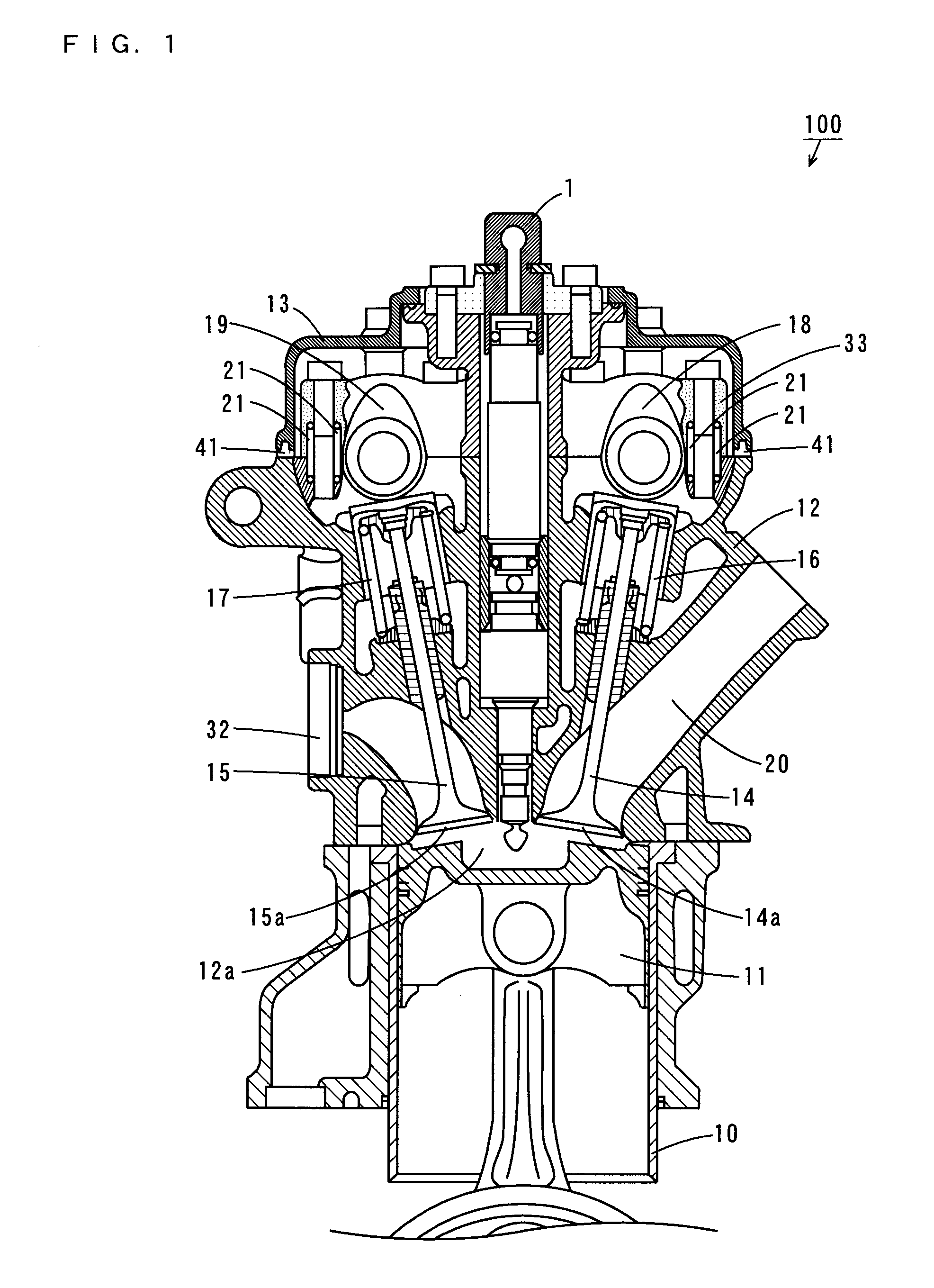
[0057]FIG. 1 is a vertical sectional view of the engine 100 according to the present preferred embodiment.

[0058]As shown in FIG. 1, the engine 100 includes a cylinder 10. A piston 11 is provided in the cylinder 10 so as to reciprocate up and down.

[0059]A cylinder head 12 is provided on the cylinder 10. The cylinder 10 and the cylinder head 12 define a combustion chamber 12a.

[0060]A cam cap 33 is mounted on the cylinder head 12 by knock pins 21. An upper portion of the cylinder head 12 is covered with a head cover 13 made of aluminum, magnesium, light alloy, fiber materials, resin or the like, for example, with an elastic member 41 made of rubber, for example, s...


PUM


Abstract

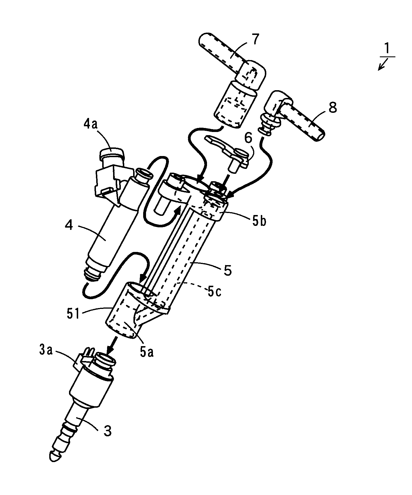
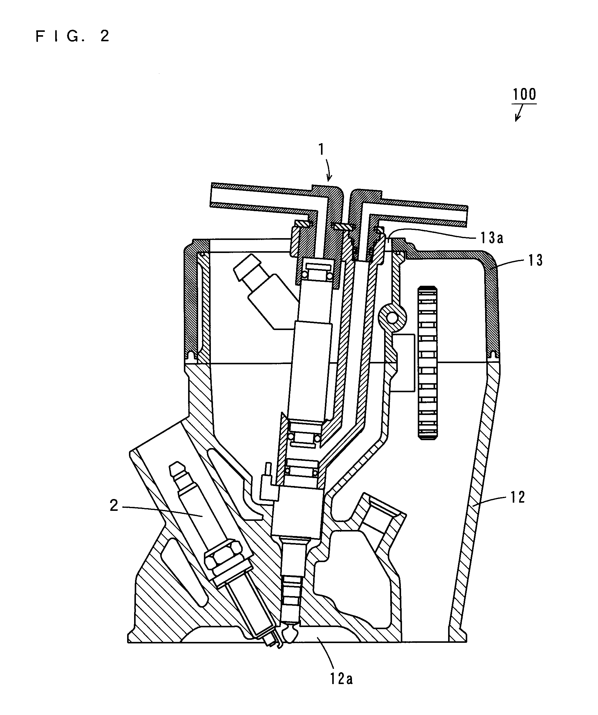
A fuel injection device includes an air-fuel mixture injector, a fuel supplier, a fuel injection device holder, an insert piece, a fuel introducer and an air introducer. The fuel injection device holder has an air-fuel mixture chamber that is provided in the inside of the fuel injection device holder and produces an air-fuel mixture by mixing supplied fuel and air, and includes a mixer provided at its one end and a connector provided at its other end. The fuel injection device holder includes an air supply passage that introduces air introduced from the air introducer into the air-fuel mixture chamber while extending between the air-fuel mixture chamber and the connector. The fuel supplier and the air-fuel mixture injector are coaxially integrated through the fuel injection device holder.

Description

BACKGROUND OF THE INVENTION[0001]1. Field of the Invention[0002]The present invention relates to a fuel injection device, an engine including the same, and a vehicle.[0003]2. Description of the Related Art[0004]In a vehicle such as a motorcycle, a fuel injection engine including a fuel injection device (injector) as a fuel supply is mounted instead of a conventional carburetor. Using this fuel injection device improves efficiency of fuel control, providing purification of exhaust gas, low-fuel consumption or other advantages.[0005]Among such fuel injection devices as the fuel supply is a fuel injection device constituted by a nozzle in communication with a combustion chamber, an air-fuel injection valve attached to a cylinder head and a fuel injection valve that is connected to this air-fuel injection valve while injecting fuel into the air-fuel injection valve (see JP 2004-060610 A, for example).[0006]In this fuel injection device, since an injector housing is integrally formed wit...

Claims


Application Information

Patent Timeline
Patent Type & Authority Applications(United States)
IPC IPC(8): F02M61/14B05B7/04
CPCF02B23/101F02M67/12F02M67/02F02M61/14
Inventor TAKASU, KOJIOKU, YUJI
Owner YAMAHA MOTOR CO LTD
Learn More