Heat-conducting assembly

a technology of heat-conducting blocks and heat-conducting components, which is applied in the direction of lighting and heating apparatus, semiconductor devices, solid-state devices, etc., can solve the problems of deterioration of heat-conducting efficiency of heat-conducting blocks, affecting the operation of electronic products or electronic elements, and affecting the life of electronic components. , to achieve the effect of improving heat-conducting efficiency, avoiding deterioration of heat-conducting efficiency

Inactive Publication Date: 2009-09-17
CHEMTRON RES
View PDF19 Cites 20 Cited by
  • Summary
  • Abstract
  • Description
  • Claims
  • Application Information

AI Technical Summary

Benefits of technology

[0011]Therefore, via the heat-conducting assembly of the present invention, the poor contact of the heat-conducting block in prior art caused by the tolerance of pitch between the heat-generating element and the heat-dissipating plate and in turn the deterioration of heat-conducting efficiency of the heat-conducting block can be avoided. Thus, the present invention indeed improves the heat-conducting efficiency and has industrial applicability.

Problems solved by technology

Accordingly, heat dissipation of an electronic product or electronic element becomes an important issue.
Insufficient heat dissipation not only affects the operation of the electronic product or the electronic element, but also affects its lifetime.
Thus, it is an important issue for those skilled in this field to improve the heat dissipation.
However, in manufacturing, a slight tolerance may be inevitably generated between individual electronic products.
Thus, the heat-conducting block cannot be adjusted finely to compensate for the slight tolerance of pitch.
As a result, if the heat-conducting block is larger than the pitch, it cannot be used.

Method used


Image

  • Heat-conducting assembly
  • Heat-conducting assembly
  • Heat-conducting assembly

Examples


first embodiment

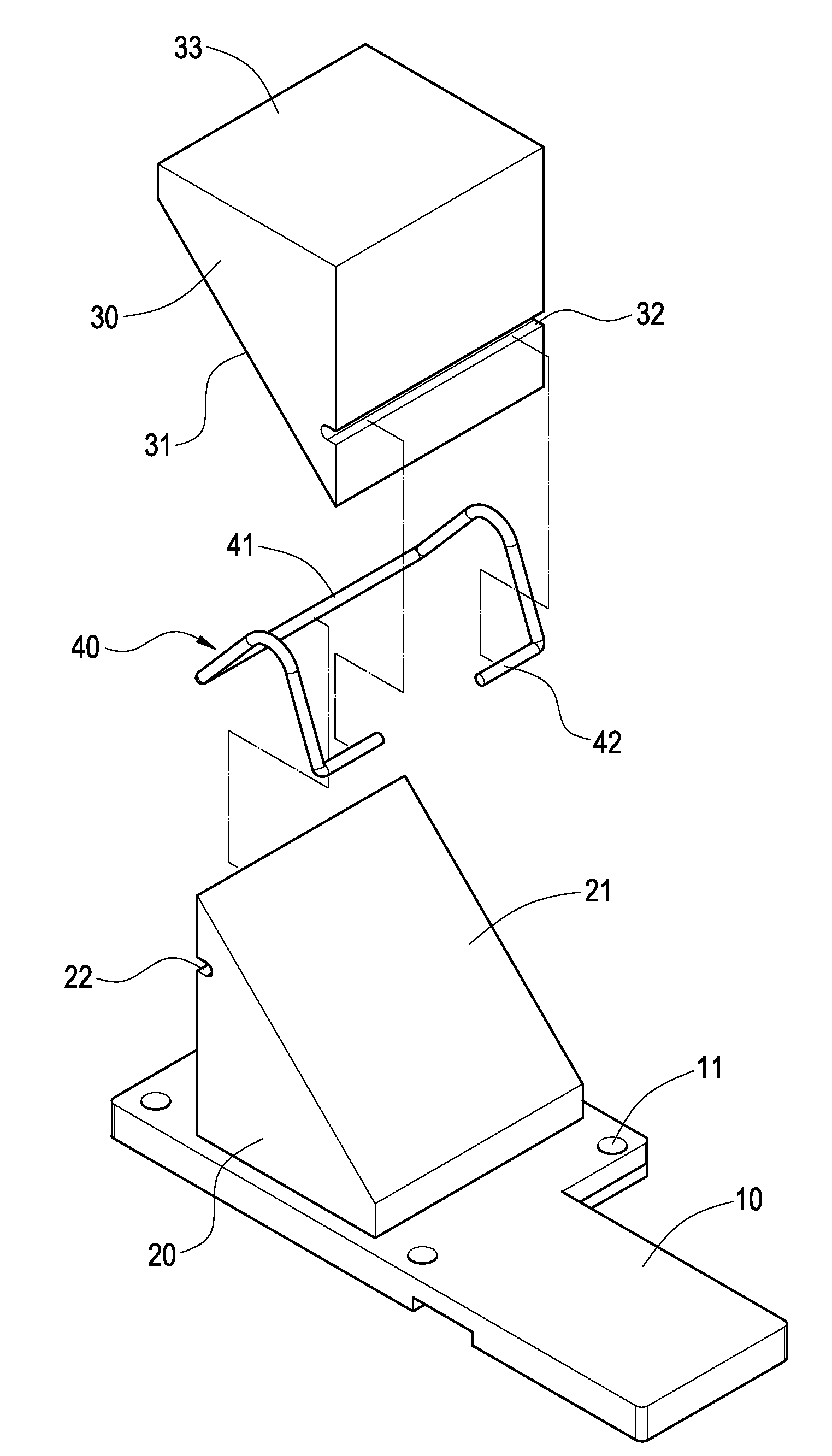
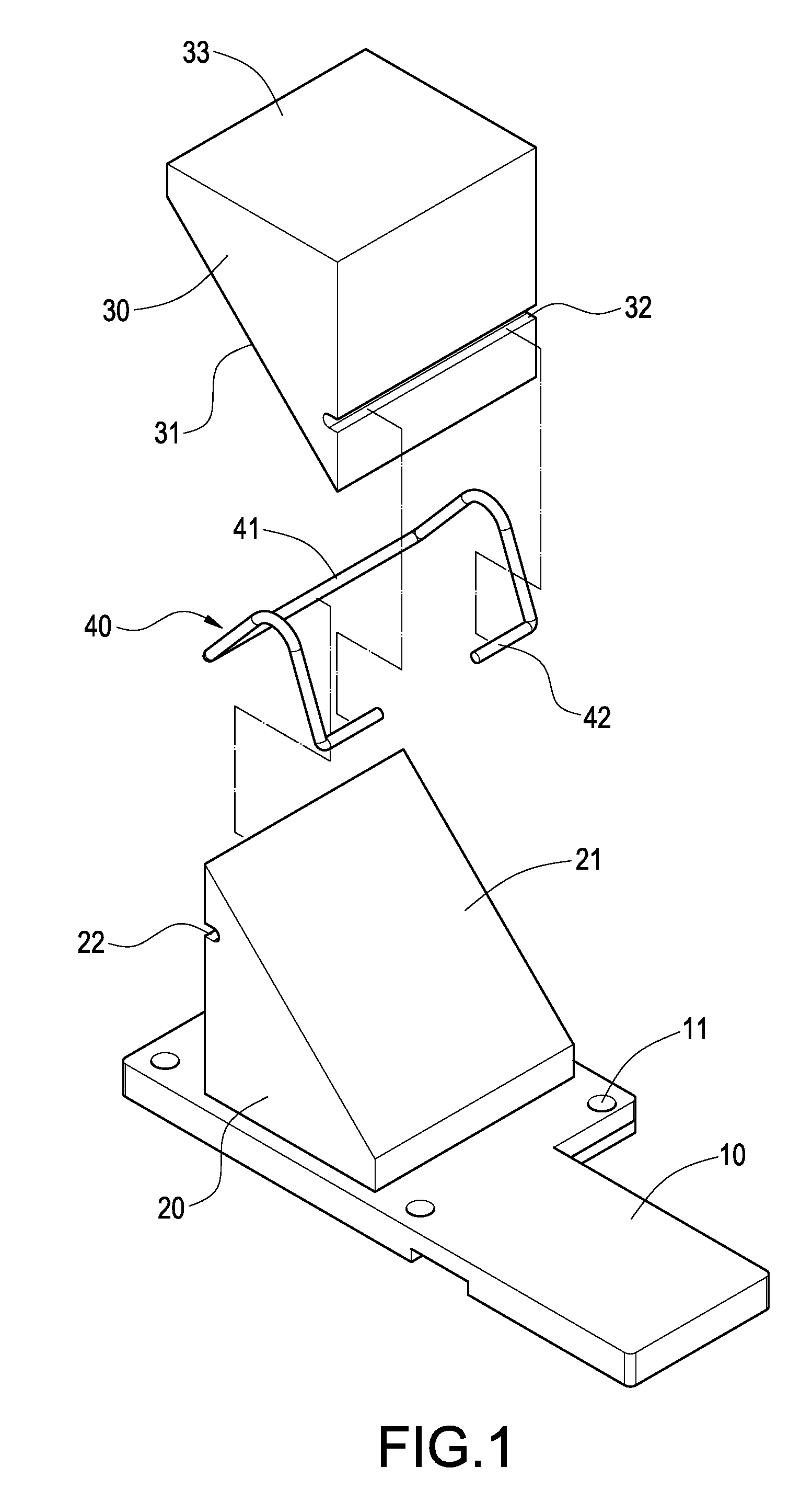
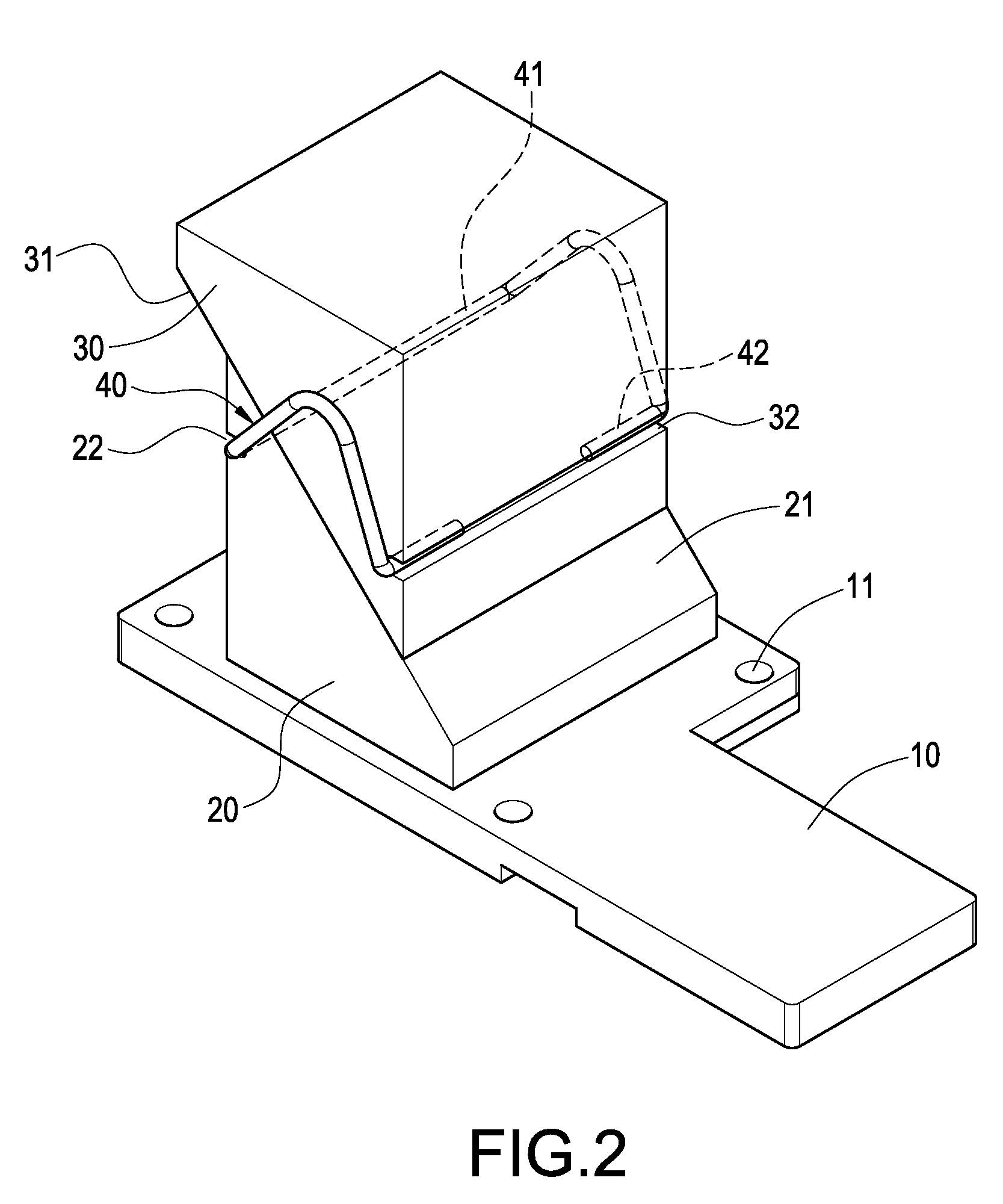
[0022]Please refer to FIGS. 1, 2 and 5. The heat-conducting assembly of the present invention is mounted in an electronic product 70. The electronic product 70 comprises a frame 71, a heat-conducting plate 72 located above the frame 71, a motherboard 73 provided on the frame 71, and a heat-generating element 74 located on the motherboard 73. The heat-conducting assembly is constituted of a base 10, a first heat-conducting block 20, a second heat-conducting block 30, and an elastic element 40.

[0023]The base 10 is attached on the heat-generating element 74. The base 10 comprises a plurality of through-holes 11 for allowing a plurality of positioning pieces 12 to pass through respectively. The positioning piece 12 may be a pin or bolt. The base 10 can be formed into an L shape. The base 10 can be formed differently based on the number and positions of the heat-generating elements 74, so that the base 10 can be applied to conduct the heat of a plurality of heat-generating elements 74. I...

second embodiment

[0030]Please refer to FIG. 6. The difference between the present embodiment and the first embodiment lies in that the elastic element 40 is a torsion spring 43 for providing a larger elastic force. Via this arrangement, the heat-conducting assembly of the present invention can abut tightly between the heat-generating element 74 and the heat-dissipating plate 72 to conduct the heat generated by the heat-generating element 74 to the heat-dissipating plate 72.

third embodiment

[0031]Please refer to FIG. 7. The heat-conducting assembly of the present invention is mounted between a heat-generating element 74 and a heat-dissipating plate 72. The heat-conducting assembly is constituted of a base 10, a first heat-conducting block 20, a second heat-conducting block 30, a fixing element 50 and an elastic body 60.

[0032]The base 10 is attached on the heat-generating element 74. The base 10 comprises a plurality of through-holes 11 for allowing a plurality of positioning pieces 12 to pass through respectively.

[0033]The first heat-conducting block 20 is disposed on the base 10. The first heat-conducting block 20 can be formed integrally with the base 10. Alternatively, the first heat-conducting block 20 and the base 10 can be formed separately and then both members are assembled together. The first heat-conducting block 20 has a first slope 21 and a fixing hole 24 penetrating the first slope 21. The fixing hole 24 is a screw hole.

[0034]The second heat-conducting blo...


PUM


Abstract

A heat-conducting assembly is mounted between a heat-generating element and a heat-dissipating plate. The heat-conducting assembly includes a base, a first heat-conducting block, a second heat-conducting block and an elastic element. The base is attached on the heat-generating element. The first heat-conducting block is provided on the base. The first heat-conducting block has a first slope and a fixing groove. The second heat-conducting block abuts on the heat-dissipating plate. The second heat-conducting block has a second slope and a locking groove. The second slope is slidingly disposed on the first slope. The elastic element has a fixed end and a buckling end formed on one side of the fixed end. The fixed end is fixed in the fixing groove, and the buckling end is buckled into the locking groove. Via this arrangement, the heat-conducting efficiency of the heat-conducting assembly of the present invention can be improved.

Description

BACKGROUND OF THE INVENTION[0001]1. Field of the Invention[0002]The present invention relates to a heat-conducting assembly, and in particular to a heat-conducting assembly that is applicable to electronic products.[0003]2. Description of Prior Art[0004]With the development of science and technology, electronic products and electronic elements are made more and more compact with a light weight. Accordingly, heat dissipation of an electronic product or electronic element becomes an important issue. Insufficient heat dissipation not only affects the operation of the electronic product or the electronic element, but also affects its lifetime. Thus, it is an important issue for those skilled in this field to improve the heat dissipation.[0005]A common electronic product, such as an industrial computer, is provided therein with a heat-generating element, a heat-dissipating plate and a heat-conducting assembly. The heat-conducting assembly is located between the heat-generating element an...

Claims


Application Information

Patent Timeline
Patent Type & Authority Applications(United States)
IPC IPC(8): F28F99/00
CPCF28D15/0233F28F3/06F28F2275/18H01L23/4338H01L2924/0002H05K7/2049H01L2924/00
Inventor CHU, CHUNG-JUN
Owner CHEMTRON RES
Why Eureka
Try Eureka