Tambourine helicopter

a helicopter and helicopter body technology, applied in the field of helicopters, can solve the problems of drooping arc condition, incurred lift factor, side stress of the rotor turret, etc., and achieve the effect of removing the condition of drooping ar

Inactive Publication Date: 2009-09-17
MCNULTY ELAINE
View PDF0 Cites 17 Cited by
  • Summary
  • Abstract
  • Description
  • Claims
  • Application Information

AI Technical Summary

Benefits of technology

[0003]The invention is a profile of a rotor wing synergistically surrounded by encasements and shrouds that eliminates the drooping arc condition of conventional rotors before they accelerate.

Problems solved by technology

Since the first helicopters, the problem of vibrations in forward movement have incurred a lift factor in the difference of the speed of the forward moving rotor blade combined with the forward speed of the craft adding to the lift on one side of the of the rotor's turret hub.
The forward moving rotor presents proportionately a small fraction of the instantaneous differences in the rotor load change however, vibration problems from the opposing sides of the rotor turret add to metal stress.

Method used


Image

  • Tambourine helicopter
  • Tambourine helicopter
  • Tambourine helicopter

Examples


Embodiment Construction

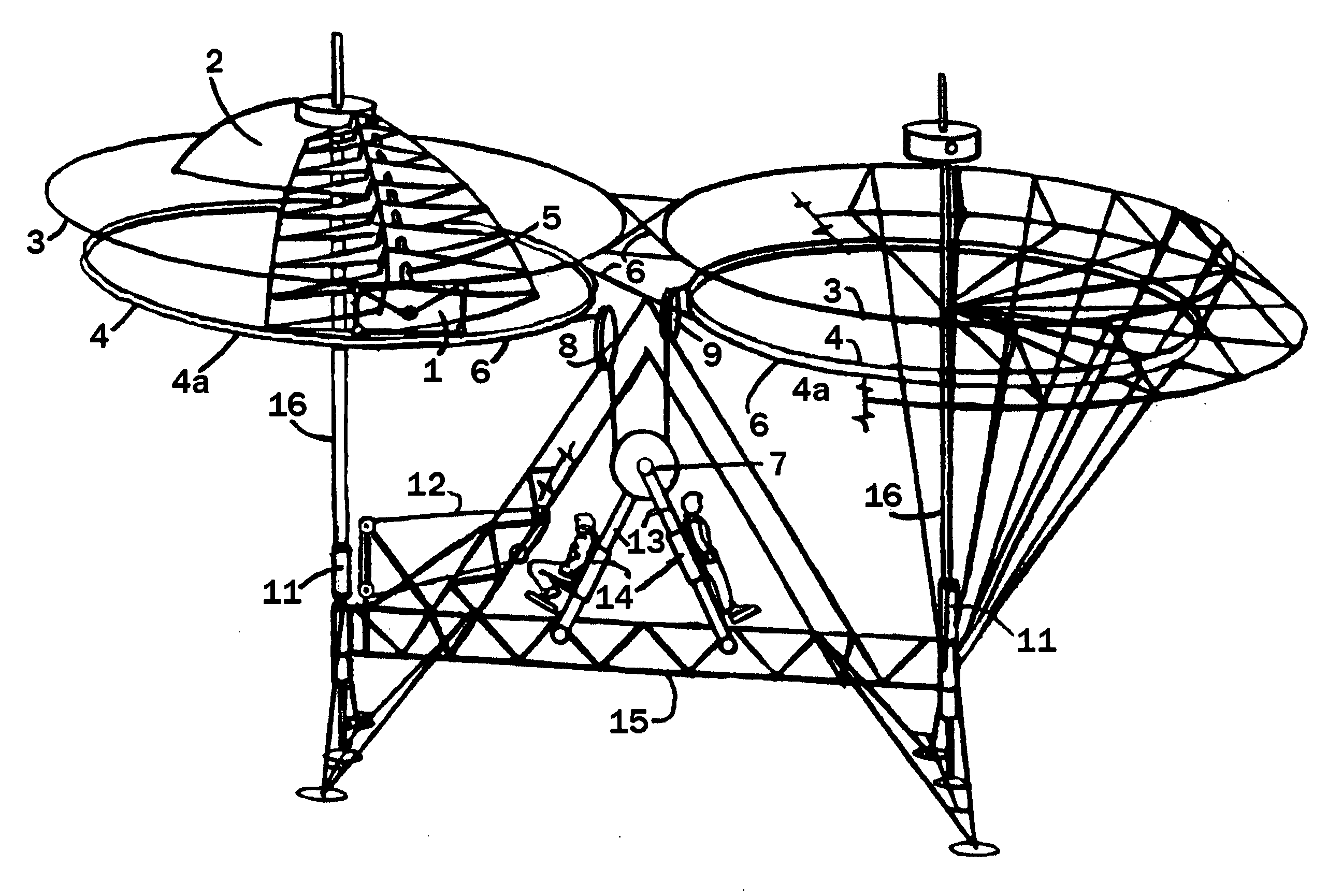
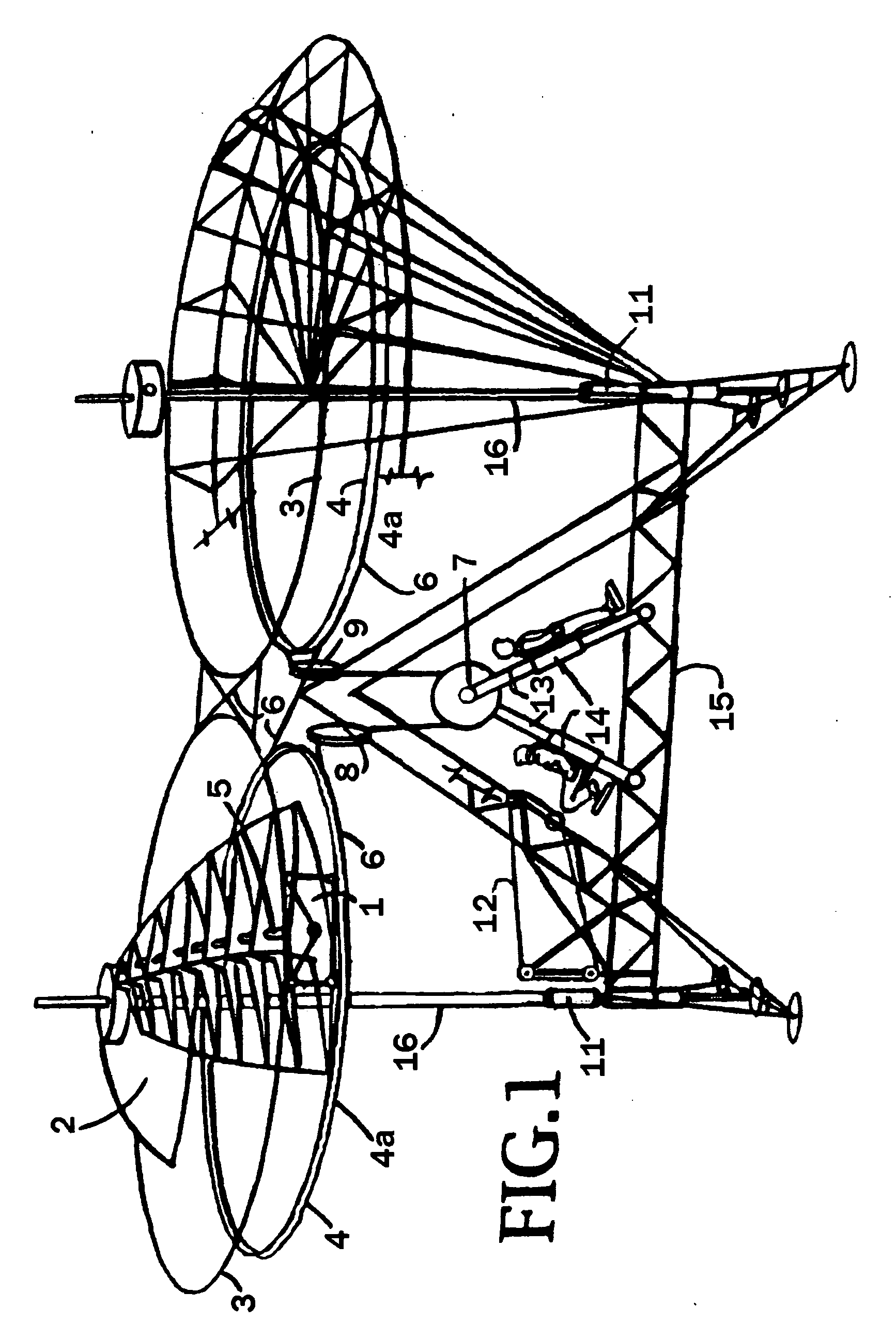
[0038]Disclosed is the profile of a helicopter, wing-rotor blade 1 synergistically applied to two helicopter fuselages, one recreational FIGS. 1. 15 and the other commercial FIGS. 16-21. 38. The commercial receives two rotor wells centrally located within said fuselage 38 that receive annularly in each well, two systems of rotors 2 and their outer FIGS. encasements, with two turrets 35 in each said well with vertical shafts 34 respectively. Means in more detailed disclosure the perimeter of each rotor blade station is formed by said rotor wells 36 that receive the base portion rotor wings FIG. 25, 2 herein called “wings”, “rotors”, “rotor-wings”, and “helicopter blades” which are shrouded concentrically by rings at their outer extremities FIGS. 32, 51, 51a, 56, and 56a which act as circular compartments or encasements that restrict the tips of the rotors FIG. 32 to stabilize an arc that approaches a Para dome configuration FIGS. 27 and 28 embodying said parachutes' lifting capabilit...


PUM


Abstract

Disclosed is a profile of an end view of a base portion Vertical Take Off And Landing Craft, (VTLC) rotor-blade comprising a widened structure from leading to trailing edges. The profile further comprises straight level planes of air foil that provide the options of transforming the leading edge to the trailing edge. The rotor wing system is housed and duplicated in the craft set within said two wells which are circumnavigated by a corridor from front to aft of the craft. Two rear exits are reinforced by the connection of a triangular structure forming a tail which also affords a comprehensive view of the complete air craft perimeter from the viewpoint of a central top compartment.

Description

BACKGROUND OF THE INVENTION[0001]Since the first helicopters, the problem of vibrations in forward movement have incurred a lift factor in the difference of the speed of the forward moving rotor blade combined with the forward speed of the craft adding to the lift on one side of the of the rotor's turret hub. The action is related to the difference of the lift between the rotor spinning in the reverse direction of the craft's forward movement, and the rotor spinning in the forward direction of the craft's forward movement. The blade moving on the back peddle direction incurs less overall forward (flight speed) therefore less lift is received from it than from the opposing rotor blade on the opposite side of the turret. The forward moving rotor presents proportionately a small fraction of the instantaneous differences in the rotor load change however, vibration problems from the opposing sides of the rotor turret add to metal stress. Because this condition even minutely exist, metal ...

Claims


Application Information

Patent Timeline
Patent Type & Authority Applications(United States)
IPC IPC(8): B64C27/08B64C27/20B64D27/00B64C1/20
CPCB64C1/00B64C3/14B64C5/02B64C27/08B64C31/04B64C27/20B64C27/32B64C27/467B64C29/0025B64C27/12
Inventor MCNULTY, NORBERT EDWARD
Owner MCNULTY ELAINE
Why Eureka
Try Eureka