Drive Device for Vehicle

a technology for driving devices and vehicles, applied in the direction of electric devices, gas pressure propulsion mountings, external condition input parameters, etc., can solve the problem of difficult suppression of the rotation of the drive shaft, and achieve the effect of accurately estimating the occurrence of the revers

Active Publication Date: 2009-09-17
TOYOTA JIDOSHA KK
View PDF4 Cites 14 Cited by
  • Summary
  • Abstract
  • Description
  • Claims
  • Application Information

AI Technical Summary

Benefits of technology

[0009]According to the above-described aspect, the drive wheel is started to be rotated backward of the vehicle when the vehicle reverses on the up-hill road against an intention of the driver. The drive shaft is rotated in association with the rotation of the drive wheel, and therefore, the rotating electric machine for allowing the vehicle to travel generates the electric power. The generation of the electric power generates torque for suppressing the rotation of the drive shaft, thereby suppressing the reverse of the vehicle. If the capacitor to be electrically charged by the electric power generated by the rotating electric machine is in a fully electrically charged state at the time of the reverse, power generation by the rotating electric machine is suppressed, and therefore, it is difficult to suppress the rotation of the drive shaft. In view of this, it is estimated whether or not the reverse occurs. If the occurrence of the reverse is estimated, the electric power electrically charged to the capacitor is electrically discharged. As a consequence, the capacitor comes into an electrically chargeable state before the reverse, and then, the capacitor can electrically charge a large electric power at the time of the reverse. In this manner, it is possible to increase the electric power generated by the rotating electric machine so as to increase the torque for suppressing the rotation of the drive shaft at the time of the reverse. Consequently, there can be provided the drive device capable of suppressing the reverse of the vehicle on the up-hill road against an intention of the driver.
[0013]According to the above-described aspect, the electric power electrically discharged by the capacitor at the time of the reverse is electrically charged to the secondary battery. As a consequence, it is possible to turn the capacitor into an electrically chargeable state by decreasing the electric power electrically charged to the capacitor without any waste of the electric power. Moreover, the secondary battery is connected to the rotating electric machine in parallel to the capacitor. Consequently, the electric power generated by the rotating electric machine at the time of the reverse can be electrically charged to the secondary battery in addition to the capacitor. In this manner, it is possible to further increase the electric power generated by the rotating electric machine at the time of the reverse, so as to further increase the torque for suppressing the rotation of the drive shaft.
[0015]According to the above-described aspect, the rotation of the drive shaft at the time of the reverse allows the second rotating electric machine to be rotated. Furthermore, the rotation of the drive shaft is transmitted to the first gear, the second gear and the third gear, thereby rotating the first rotating electric machine. As a consequence, the first rotating electric machine also generates the electric power in addition to the second rotating electric machine. Therefore, it is possible to further increase the torque for suppressing the rotation of the drive shaft in comparison with a case where the electric power is generated by a single rotating electric machine.
[0017]According to the above-described aspect, the drive wheel is started to be rotated backward of the vehicle when the vehicle reverses on the up-hill road against an intention of the driver. The drive shaft is rotated in association with the rotation of the drive wheel, and therefore, the second rotating electric machine connected to the drive shaft and the first rotating electric machine connected to the drive shaft via the distributing mechanism generates AC electric power. The generation of the electric power generates torque for suppressing the rotation of the drive shaft, thereby suppressing the reverse of the vehicle. The AC electric power generated by the first rotating electric machine and the second rotating electric machine is converted into DC electric power by the first inverter and the second inverter, respectively. The converted DC electric power is electrically charged to the capacitor, and further, the voltage is stepped down by the converter, to be electrically charged to the secondary battery. If the capacitor is in a fully electrically charged state at the time of the reverse, the converted DC electric power cannot be electrically charged to only the secondary battery. In view of this, the power generation by the first rotating electric machine and the second rotating electric machine is suppressed, and therefore, it is difficult to suppress the rotation of the drive shaft. In view of this, it is estimated whether or not the reverse occurs. If the occurrence of the reverse is estimated, the converter is controlled in such a manner as to step down the voltage input from the side of the capacitor, and then, to output it onto the side of the secondary battery. In this manner, the electric power at the capacitor is electrically discharged, and thus, the secondary battery is electrically charged. As a consequence, it is possible to turn the capacitor into an electrically chargeable state by decreasing the electric power electrically charged to the capacitor without any waste of the electric power before the reverse. Thus, the capacitor can electrically charge a large electric power at the time of the reverse. At the time of the reverse, it is possible to increase the electric power generated by the first rotating electric machine and the second rotating electric machine, so as to increase the torque for suppressing the rotation of the drive shaft. Consequently, there can be provided the drive device capable of suppressing the reverse of the vehicle on the up-hill road against an intention of the driver.
[0019]According to the above-described aspect, the amount of electric energy electrically charged to the capacitor is calculated based on the voltage of the capacitor. If the occurrence of the reverse is estimated, the converter is controlled in such a manner as to step down the voltage to be input from the side of the capacitor, to output it onto the side of the secondary battery until the calculated amount of electric energy becomes the predetermined value or lower. Thus, the capacitor can electrically charge the large electric power at the time of the reverse by decreasing the amount of electric energy electrically charged to the capacitor before the reverse.
[0021]According to the above-described aspect, it is estimated whether or not the reverse occurs based on the gradient of the up-hill road, the brake pedaling. force and the vehicular speed. For example, it is estimated that the reverse occurs when the vehicular speed is almost zero upon request for braking by the driver on the up-hill road whose gradient is greater than a predetermined value. Thus, it is possible to accurately estimate the occurrence of the reverse.

Problems solved by technology

If the capacitor to be electrically charged by the electric power generated by the rotating electric machine is in a fully electrically charged state at the time of the reverse, power generation by the rotating electric machine is suppressed, and therefore, it is difficult to suppress the rotation of the drive shaft.

Method used


Image

  • Drive Device for Vehicle
  • Drive Device for Vehicle
  • Drive Device for Vehicle

Examples


first embodiment

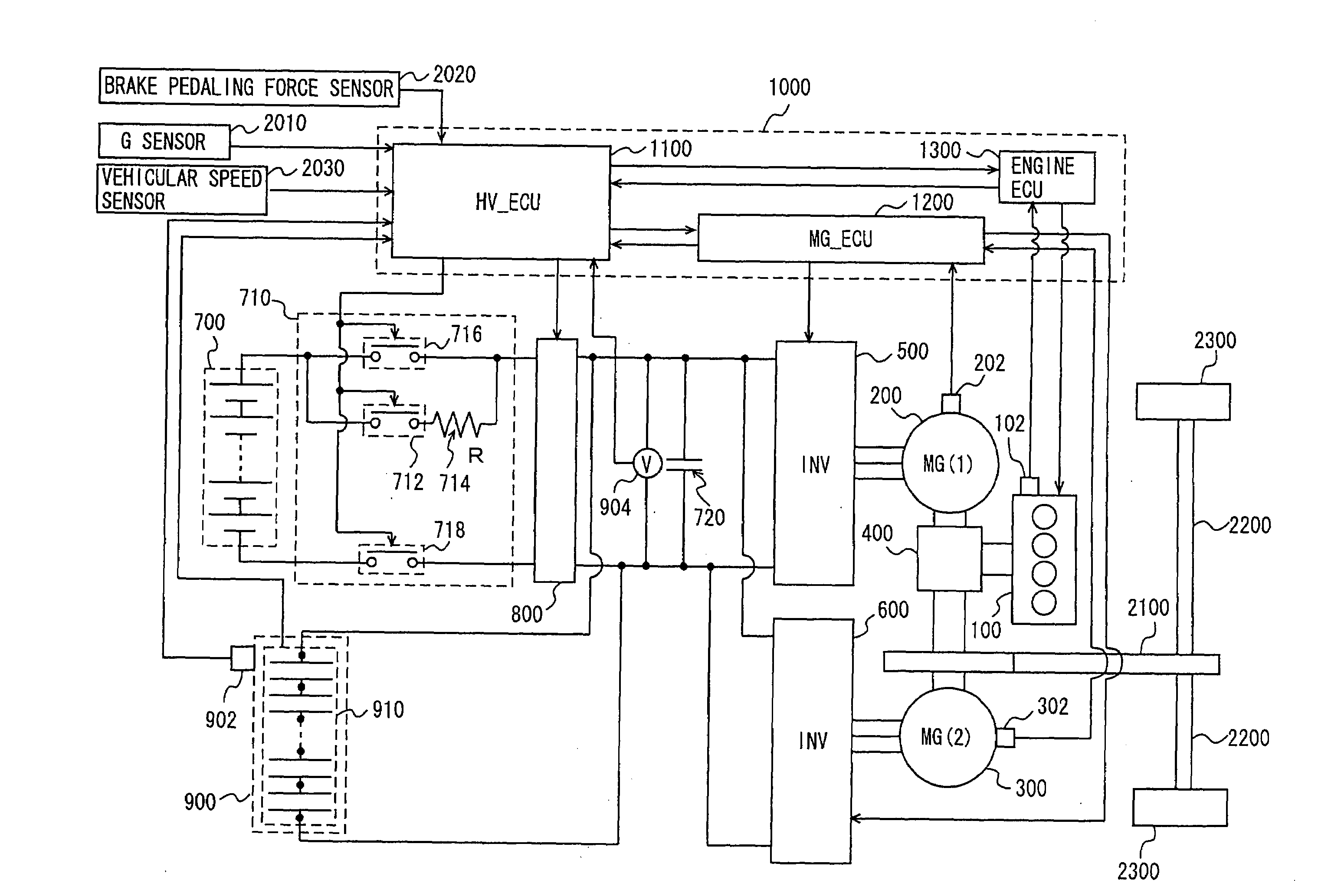
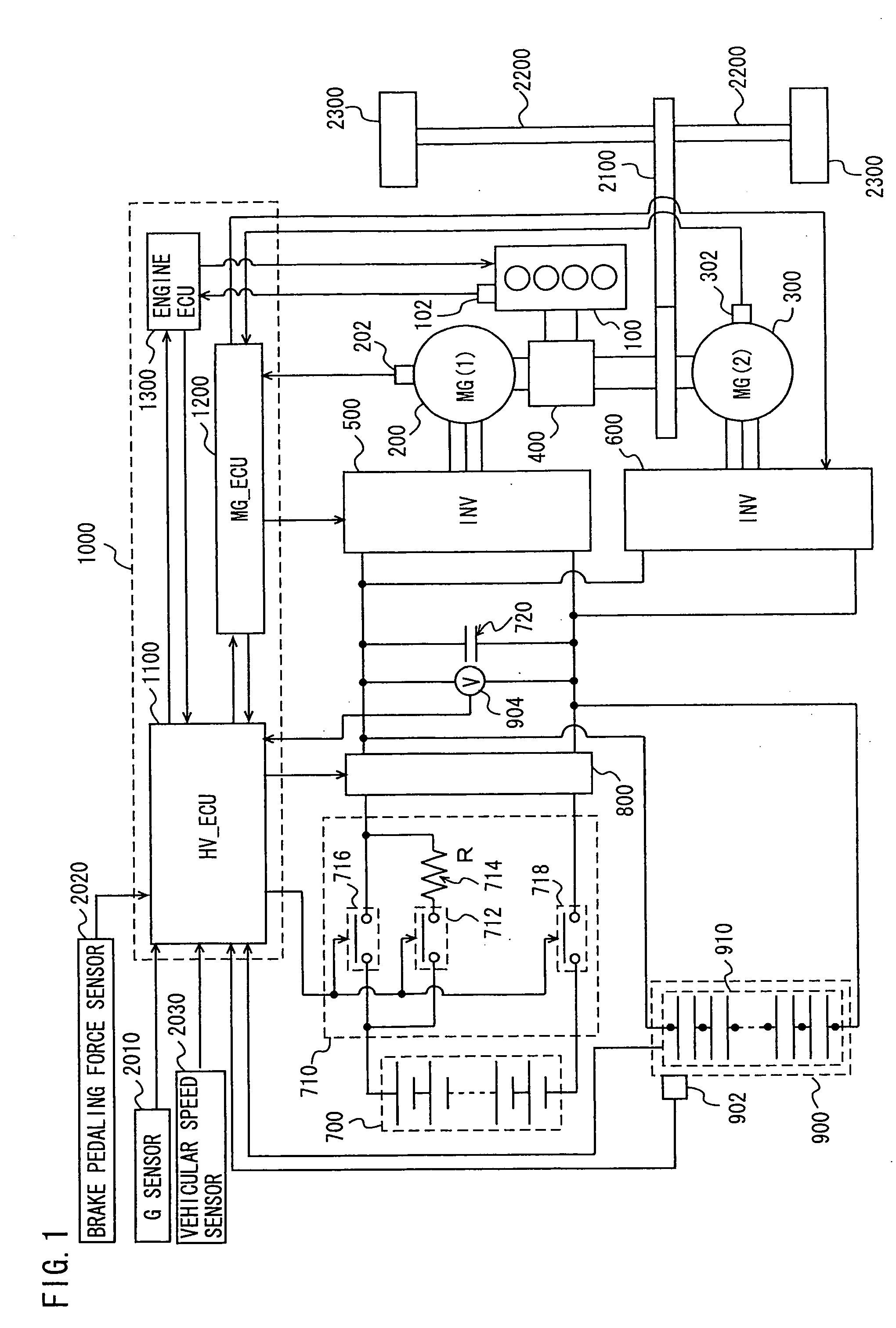
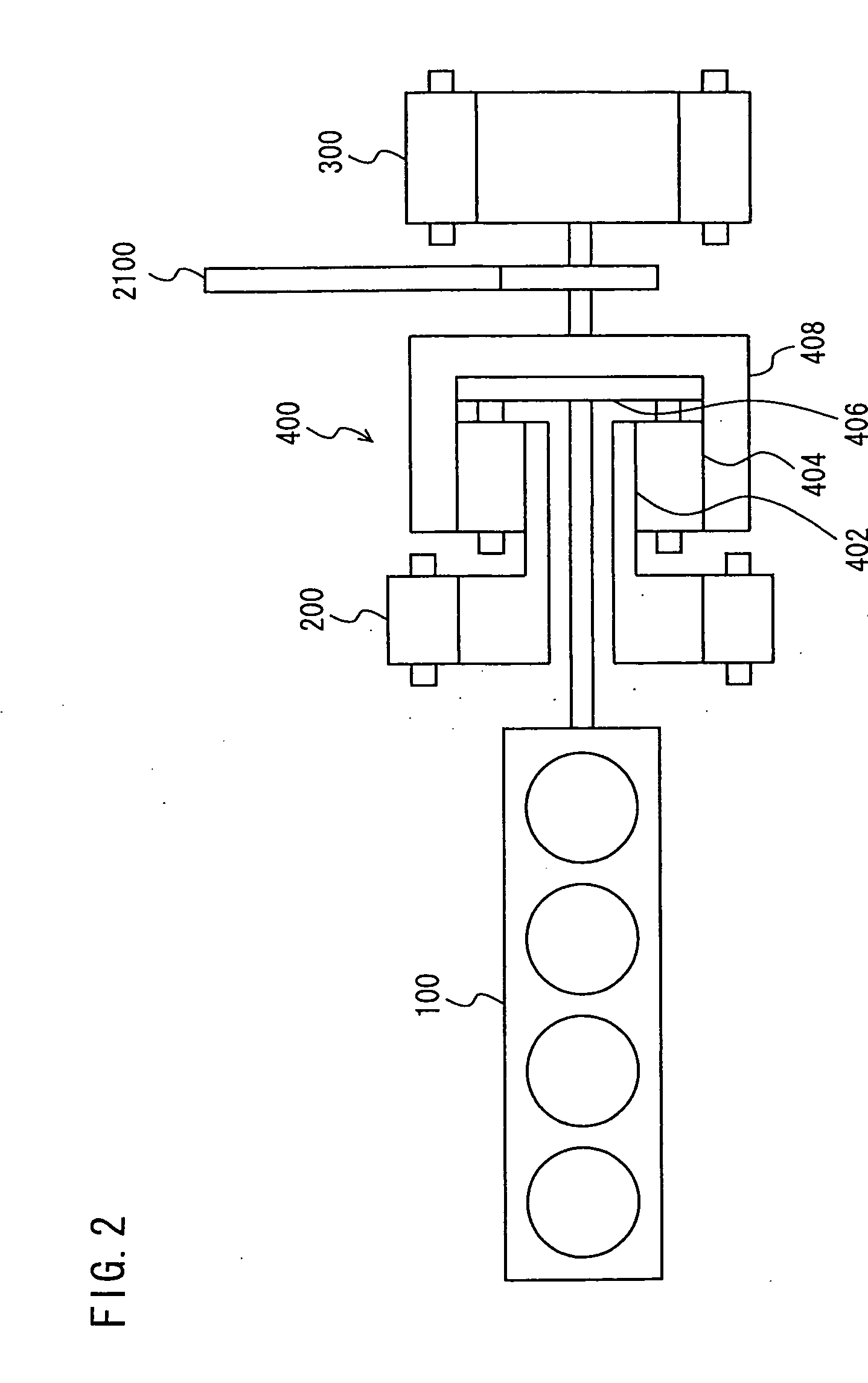
[0029]Referring to FIG. 1, description will be given below of a hybrid vehicle having a drive device mounted thereon in the present embodiment. The vehicle includes: an engine 100, an MG (abbreviating “a motor generator”) (1) 200, an MG (2) 300, a power split device 400, an inverter (1) 500, an inverter (2) 600, a battery 700, a converter 800, a capacitor 900, a speed reducer 2100, a drive shaft 2200 and drive wheels 2300. The vehicle travels with drive force from at least either one of engine 100 and MG (2) 300.

[0030]Engine 100, MG (1) 200 and MG (2) 300 are connected to each other via power split device 400. Power generated by engine 100 is split into two channels by power split device 400. On one of the channels, drive wheels 2300 are driven via speed reducer 2100 and drive shaft 2200. On the other channel, MG (1) 200 is driven, thereby generating electric power.

[0031]MG (1) 200 is a three-phase AC motor. MG (1) 200 generates the electric power by the power of engine 100, split b...


PUM


Abstract

An object of the present invention is to suppress reverse of a vehicle on an up-hill road against an intention of a driver. A drive device for a vehicle according to the present invention includes: an estimator for estimating whether or not reverse of the vehicle occurs on an up-hill road; a rotating electric machine for generating electric power by rotation of a drive wheel in the vehicle when the vehicle reverses; a capacitor for electrically charging the electric power generated by the rotating electric machine; and a battery connected in parallel to the capacitor, wherein the estimator estimates that the reverse of the vehicle occurs when a current traveling road is an up-hill road and a vehicular speed is smaller than a threshold whereas the electric power of the capacitor is electrically discharged to the battery when the reverse of the vehicle is estimated and the amount of electric energy of the capacitor is greater than a certain threshold.

Description

TECHNICAL FIELD[0001]The present invention relates to a drive device for a vehicle provided with a rotating electric machine for traveling and, more particularly, to a technique for electrically charging a capacitor with electric power generated by a rotary electric machine.BACKGROUND ART[0002]Attention has been recently directed to a hybrid vehicle which travels by drive force from at least either one of an engine and a motor as part of measures for environmental issues. On such a hybrid vehicle is mounted a capacitor (i.e., a condenser) or the like for accumulating electric power to be supplied to the motor. Japanese Patent Laying-Open No. 2005-061498 discloses a hybrid vehicle having such a battery or such a capacitor mounted thereon.[0003]The hybrid vehicle disclosed in Japanese Patent Laying-Open No. 2005-061498 includes: an engine; a first motor generator for exhibiting both of a function of an electric motor and a function of a power generator, a power distributing mechanism ...

Claims


Application Information

Patent Timeline
Patent Type & Authority Applications(United States)
IPC IPC(8): H02P31/00H02J7/00B60L50/16
CPCB60K1/02Y02T10/6239B60K6/365B60K6/445B60L3/0046B60L11/005B60L11/123B60L11/14B60L2210/40B60L2240/642B60L2270/20B60W10/08B60W10/26B60W20/00B60W30/18118B60W2510/244B60W2520/10B60W2540/12B60W2550/142F16H2037/0866Y02T10/6217Y02T10/6278Y02T10/7005Y02T10/7022Y02T10/7077Y02T10/7291Y02T90/16Y02T10/7241B60Y2400/114B60K6/28B60L50/16B60L50/40B60L50/61B60L58/12B60W2552/15Y02T10/62Y02T10/70Y02T10/7072Y02T10/72B60W20/13
Inventor SOMA, TAKAYAYOSHIDA, HIROSHIMOGARI, TAKESHISAWADA, HIROKI
Owner TOYOTA JIDOSHA KK
Why Eureka
Try Eureka