
Liquid ejecting head and liquid ejecting apparatus

Active Publication Date: 2009-09-17
SEIKO EPSON CORP
View PDF2 Cites 0 Cited by
  • Summary
  • Abstract
  • Description
  • Claims
  • Application Information

AI Technical Summary

Benefits of technology

[0011]According to the first aspect of the invention, the adhesive layer in the area corresponding to the second area of the reservoir unit is provided so as to be apart outside from the end face of the second area by a predetermined distance, and the width of the compliance unit corresponding to the second area is formed larger than the width of the second area. It is known that the width of the compliance unit and an absorption amount of the energy of the pressure wave caused by pressure change of each pressure generating chamber has a positive correlation. Accordingly, the energy of the pressure wave cased by the pressure change of each pressure generating chamber can be well absorbed than before. Accordingly, a liquid ejecting head equipped with good liquid ejection property can be obtained.
[0015]In this case, in the compliance unit, the width corresponding to the second area of the reservoir unit is formed so as to be the same as the width corresponding to the first area of the reservoir unit. Herewith, the deformation amount of the compliance unit in the second area becomes the same as the deformation amount of the compliance unit at the center of the reservoir unit in the arrangement direction of the pressure generating chambers. Accordingly, also in the second area, similarly to the first area, the energy of the pressure wave caused by presser change of each pressure generating chamber can be well absorbed.
[0016]Specifically, unevenness between the first area and the second area disappears in the absorption amount of the energy of the pressure wave cased by the pressure change of each pressure generating chamber. Accordingly, a liquid ejecting head that smoothes flow of ink by the second area of the reservoir unit and prevents retention of bubbles, and that has good ink ejection property can be obtained.
[0019]In this case, the distance between one end face of the reservoir unit in the second area and the adhesive layer outside thereof, and the distance between the other end face and the adhesive layer outside thereof in a cross section in the direction perpendicular to the arrangement direction of the pressure generating chambers are set so as to be the same. Herewith, the compliance unit is provided so that each of the ends in the second area is apart from each of the end faces in the second area perpendicular to the arrangement direction of the pressure generating chambers by the same distance in the direction perpendicular to the arrangement direction of the pressure generating chambers. When the compliance unit is provided in this manner, it is prevented that bubbles are retained at any one side of the compliance unit in the direction perpendicular to the arrangement direction of the pressure generating chambers. Accordingly, bubbles can be speedy discharged even when bubbles are generated in the reservoir unit.
[0022](5) According to the second aspect of the invention, ink ejection property is improved and uniformized and the ink jet type recording apparatus whose print quality is improved can be obtained.

Problems solved by technology

The pressure wave is transmitted to another pressure generating chamber via the reservoir to cause unevenness of ink ejection property such as change of liquid drop speed.
When the both ends of the reservoir in the alignment direction of the pressure generating chambers are formed by the same width as that of the other portion of the reservoir, flow speed of the ink supplied from the center becomes slow as the ink comes close to the both ends in the alignment direction of the pressure generating chambers, and this may cause retention of bubbles at the both ends.
Accordingly, in such an ink jet type recording head, good ink ejection property can not be obtained.
Note that such a problem exists not only in the ink jet type recording head, but also in a liquid ejecting head that ejects liquid except ink in the same manner.

Method used


Image

  • Liquid ejecting head and liquid ejecting apparatus
  • Liquid ejecting head and liquid ejecting apparatus
  • Liquid ejecting head and liquid ejecting apparatus

Examples


first embodiment

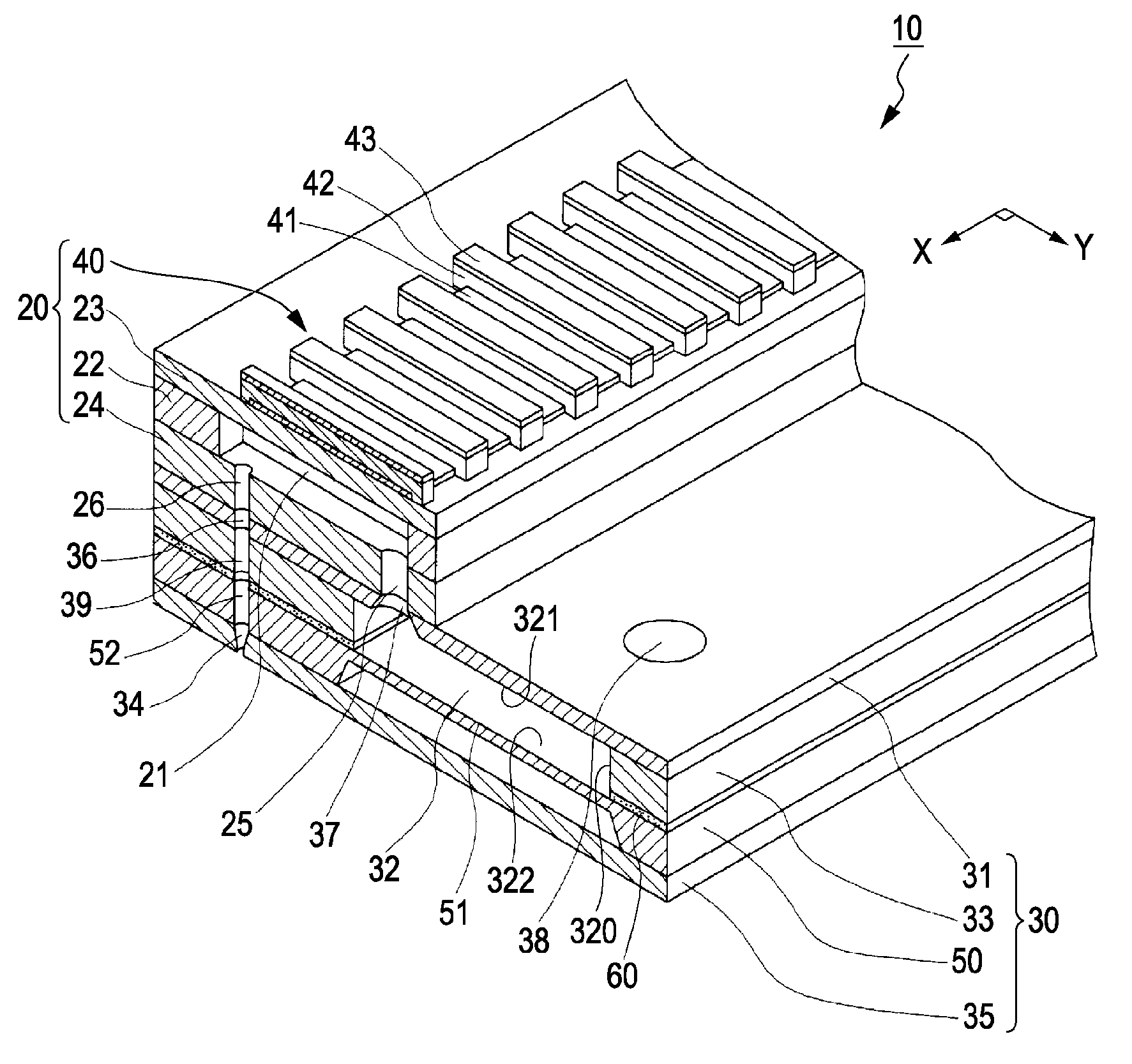
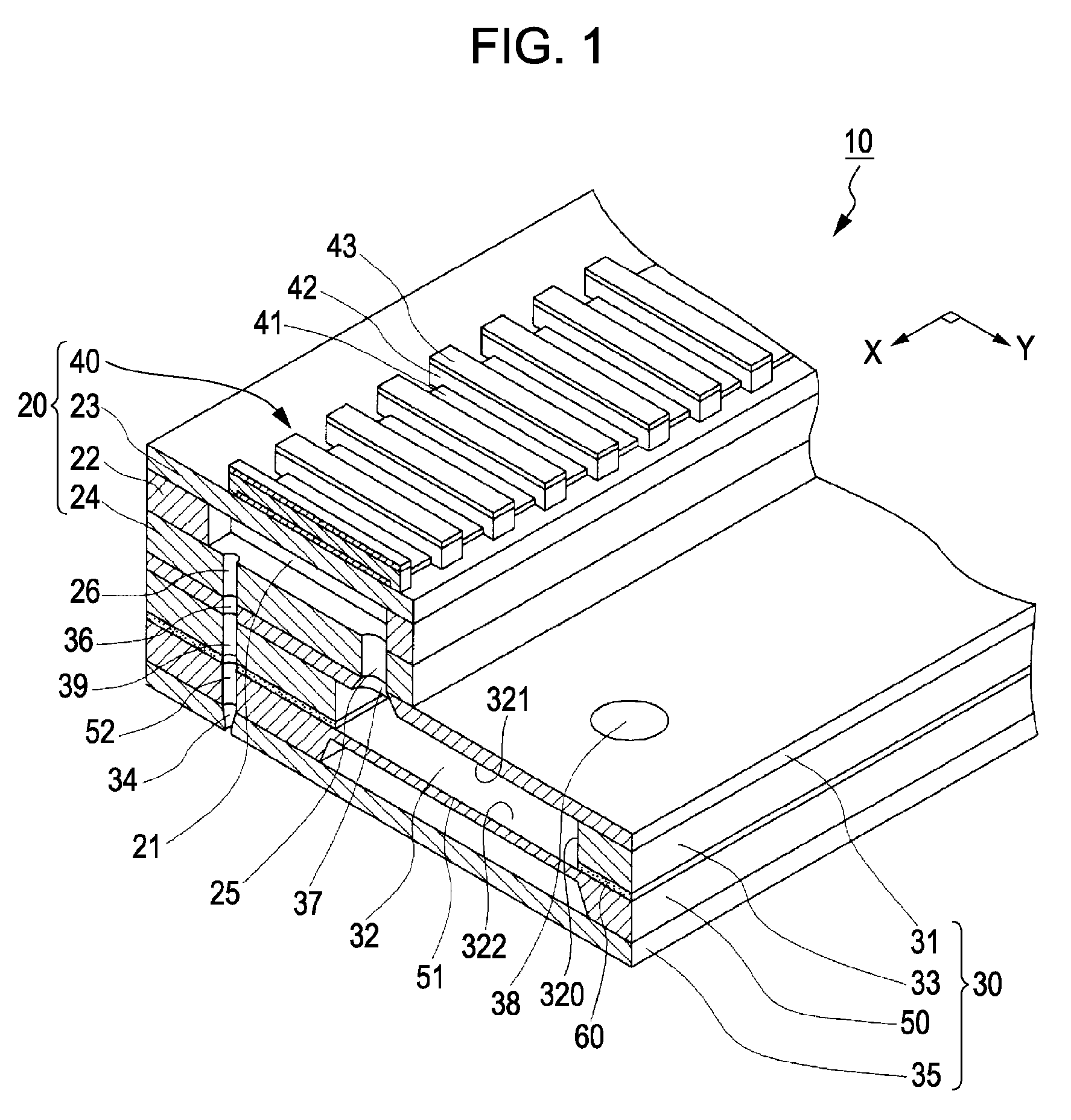
[0035]FIG. 1 is a cut-out perspective view showing a main portion of an ink jet type recording head 10 as a liquid ejecting head of the embodiment.

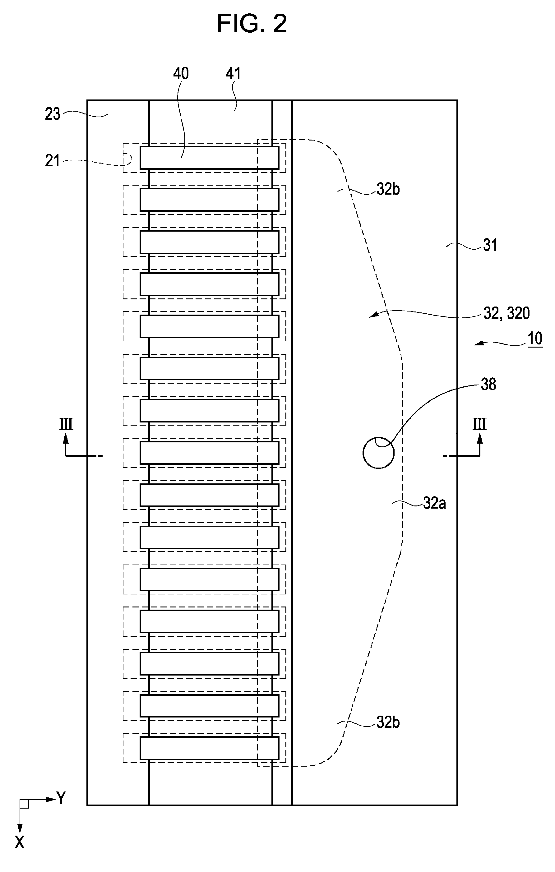
[0036]FIG. 2 is a plan view showing the ink jet recording head. FIG. 3 is a cross sectional view taken along the line III-III of FIG. 2.

[0037]In FIGS. 1 to 3, the ink jet type recording head 10 of the embodiment is equipped with an actuator unit 20, and a channel unit 30 to which the actuator unit 20 is fixed.

[0038]The actuator unit 20 is an actuator device equipped with piezoelectric elements 40. The actuator unit 20 is equipped with a channel forming substrate 22 in which pressure generating chambers 21 are formed, a diaphragm 23 provided at one face side of the cannel forming substrate 22, and a pressure generating chamber bottom plate 24 provided at the other face side of the channel forming substrate 22.

[0039]A plurality of the pressure generating chambers 21 are formed in the channel forming substrate 22 so as to be arranged in para...

second embodiment

[0084]FIG. 8 is a diagram schematically showing an example of an ink jet type recording apparatus I according to the embodiment.

[0085]The ink jet type recording heads 10, 10A of the first embodiment and the modification constitute a part of recording head units 1A, 1B that are equipped with an ink channel communicated with a cartridge or the like that is an ink tank, and are mounted in the ink jet type recording apparatus I that is a liquid ejecting apparatus.

[0086]In FIG. 8, in the recording head units 1A, 1B of the ink jet type recording apparatus I, cartridges 2A and 2B as ink tanks constituting ink supply means are detachably provided. A carriage 3 on which the recording head units 1A and 1B are mounted is provided on a carriage axis 5 attached to a device main body 4 so as to be moved in the axis direction. The recording head units 1A and 1B respectively ejects, for example, a black ink composition and a color ink composition.

[0087]A driving force of a driving motor 6 is transm...


PUM


Abstract

There is provided a liquid ejecting head including a plurality of pressure generating chambers, a first substrate having a reservoir unit, and a second substrate having a compliance unit, the second substrate being combined with one surface of the first substrate via an adhesive layer. The reservoir unit has a first area and a second area whose width in a direction perpendicular to the arrangement direction of the pressure generating chambers is smaller than a width of the first area, the compliance unit is provided to seal the reservoir unit and the surrounding of the compliance unit is fixed by the adhesive layer, and a width of the compliance unit corresponding to the second area of the reservoir unit is formed so as to be larger than the width of the second area.

Description

BACKGROUND[0001]1. Technical Field[0002]The present invention relates to a liquid ejecting head and a liquid ejecting apparatus that eject liquid from a nozzle orifice, and in particular to an ink jet type recording head and an ink jet type recording apparatus that eject ink as liquid.[0003]2. Related Art[0004]There has been know an ink jet type recording head that is an example of a liquid ejecting head equipped with, for example, an actuator unit in which piezoelectric elements and pressure generating chambers are provided, and a channel unit equipped with a nozzle plate in which nozzle orifices that are communicated with the pressure generating chambers and that eject ink is provided and reservoir forming substrate in which a reservoir that becomes a common ink chamber of the pressure generating chambers is provided (for example, see JP-A-2004-042559 (pages 6 to 8, FIGS. 1 to 2).[0005]In such a type of ink jet type recording head, when a pressure is applied to the ink in the pres...

Claims


Application Information

Patent Timeline
IPC IPC(8): B41J29/38
CPCB41J2/055B41J2202/11B41J2002/14419B41J2/14233
Inventor OKUBO, KATSUHIRO
Owner SEIKO EPSON CORP
Features
  • Generate Ideas
  • Intellectual Property
  • Life Sciences
  • Materials
  • Tech Scout
  • Unparalleled Data Quality
  • Higher Quality Content
  • 60% Fewer Hallucinations
Learn More