Imaging apparatus

a technology of imaging apparatus and acoustic field, which is applied in the direction of television system, exposure control, instruments, etc., can solve the problems of large arithmetic processing time, inability to obtain appropriate synthetic images, and long processing time, so as to reduce the influence of displacement and reduce the processing time of synthesis processing. , the effect of wide dynamic rang

Active Publication Date: 2009-09-17
RICOH KK
View PDF25 Cites 40 Cited by
  • Summary
  • Abstract
  • Description
  • Claims
  • Application Information

AI Technical Summary

Benefits of technology

[0010]At least an object of the present invention is to provide, for example, an imaging apparatus in which when synthesizing a plurality of image data, the influence of displacement is decreased utmostly, and the processing time of synthesis processing is reduced, and an image a with wide dynamic range is obtained.

Problems solved by technology

However, in the imaging apparatus disclosed by JP-3674420 B, if there is displacement between the plurality of images, an appropriate synthetic image can not be obtained.
In addition, in the imaging apparatus disclosed by JP-3788714 B, due to the amount of image blur of the main subject and the other amount of image blur being detected by the image blur detecting device, and synthetic image information being built with the plurality of image information at the part where the amount of image blur is equal to or less than the prescribed value, and synthetic image information being built with information of one image at the part where the amount of image blur is more than the prescribed value, problems arise such as arithmetic processing being enormous, processing time being long, and the apparatus being impractical.

Method used


Image

  • Imaging apparatus
  • Imaging apparatus
  • Imaging apparatus

Examples


first embodiment

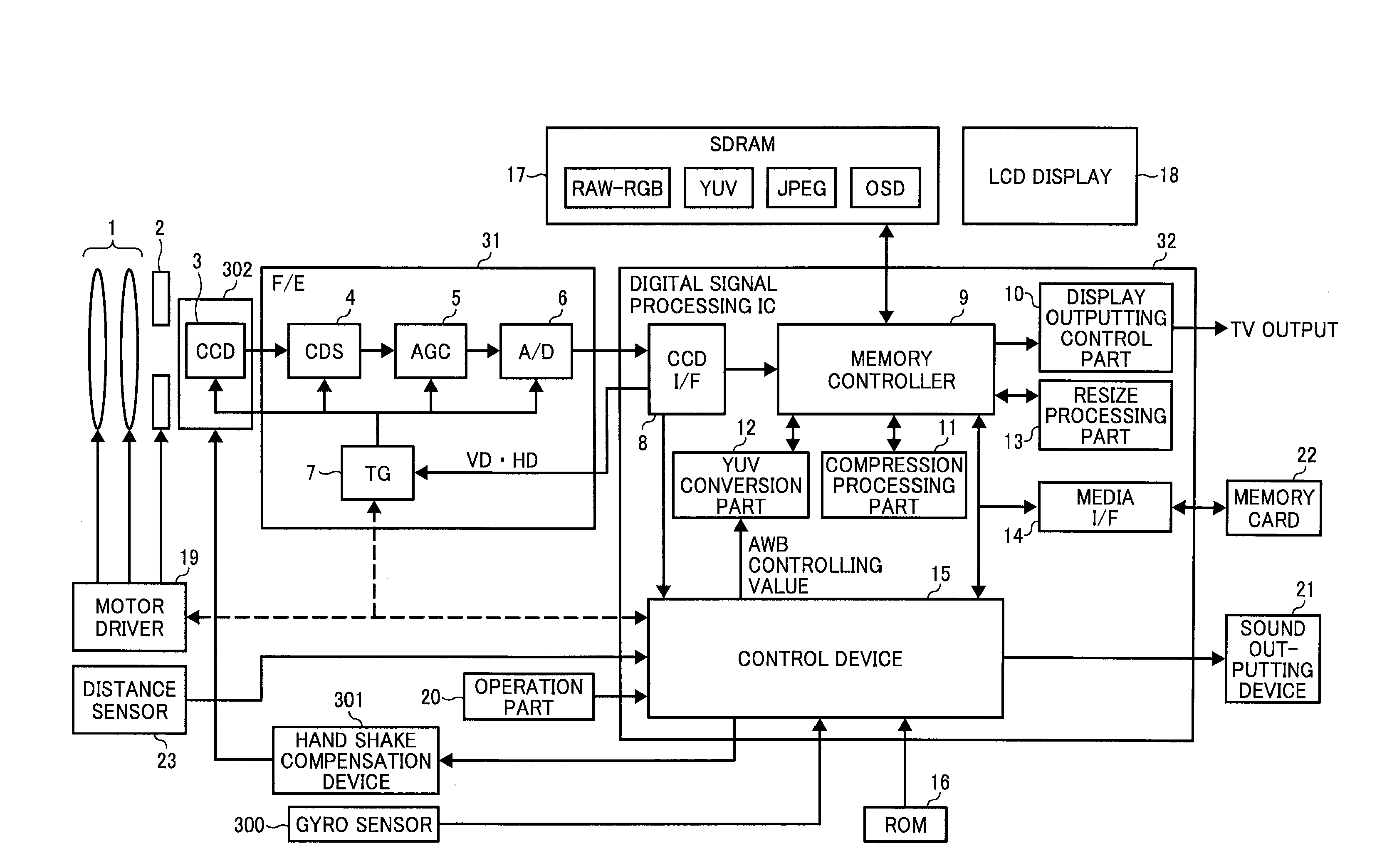
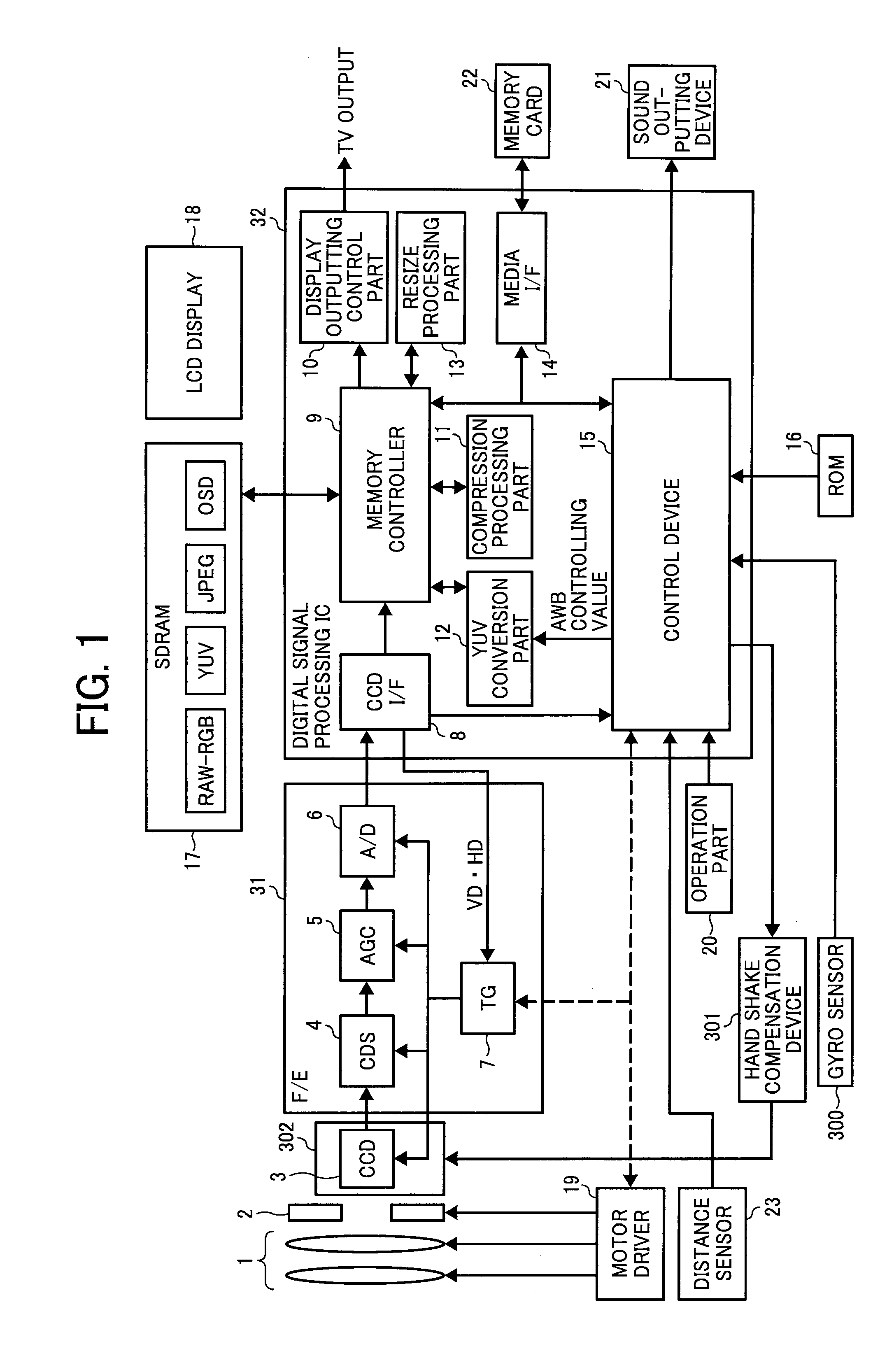
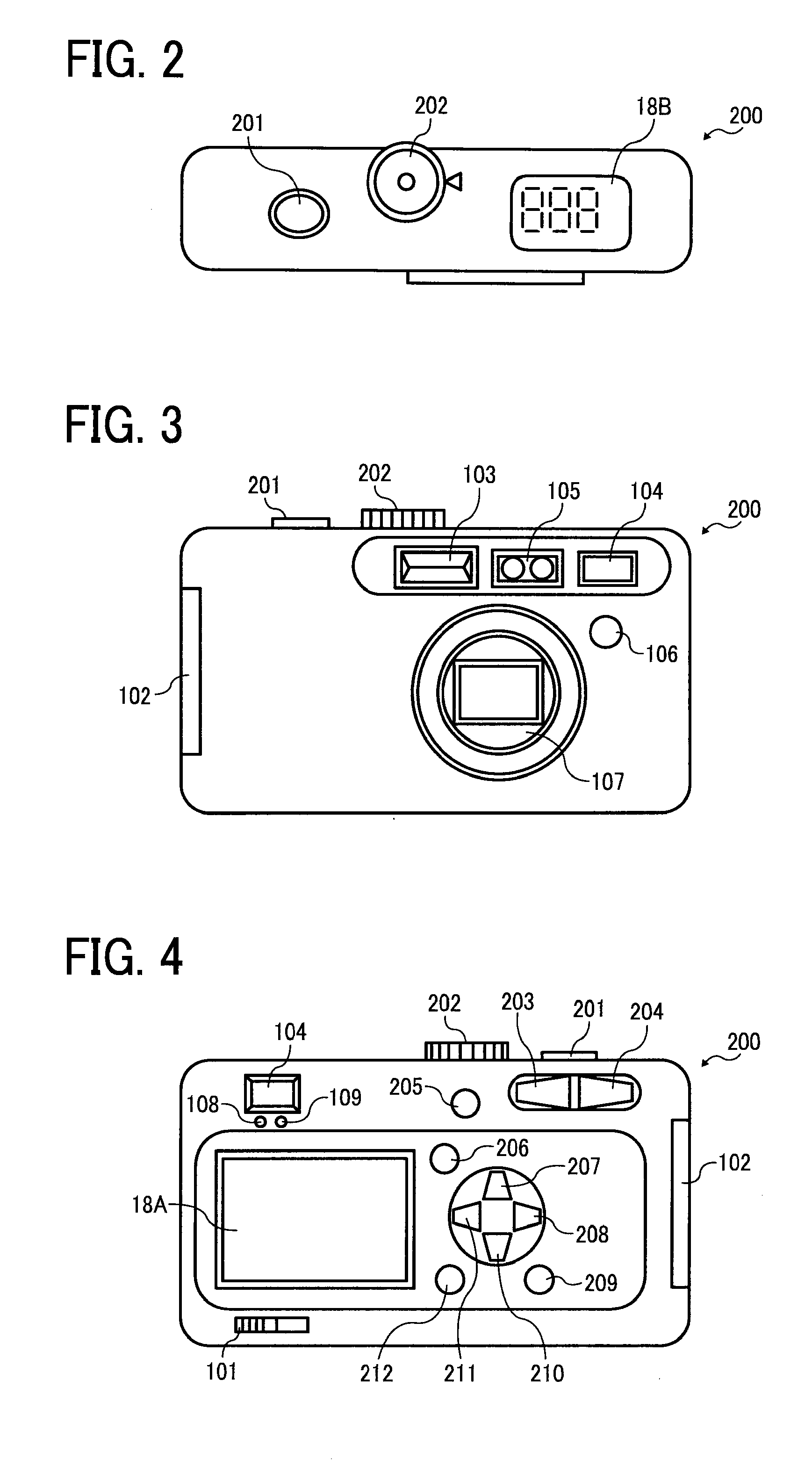
[0023]FIGS. 1, 2, 3 and 4 are views, each of which illustrates a structure of a digital still camera according to an embodiment of the present invention, FIG. 1 is a block diagram illustrating a schematic view of a whole system structure of the digital still camera. FIGS. 2-4 are views, each of which schematically illustrates an outline of the camera illustrated in FIG. 1, where FIG. 2 illustrates a plan view, FIG. 3 illustrates a front view, and FIG. 4 illustrates a back view, respectively. The digital still camera illustrated in FIG. 1 includes: a photographing lens system (a photographing optical system) 1 having a focus lens (a focus optical system); a CCD3 (an image pickup device) which is configured to capture an image projected through the photographing lens system 1; a mechanical shutter 2 which is arranged between the photographing lens system 1 and the CCD3; a motor driver 19 which is configured to displace at least a focus lens of the photographing lens system 1 along an ...

second embodiment

[0080]FIG. 7 is a flow chart illustrating a processing operation of the second embodiment. Operations of the second embodiment will be explained with reference to the flow chart.

[0081]In step 10, the mechanical shutter 2 is controlled and a first short time exposure imaging is performed. An exposure time of the first short time exposure imaging, for example, is 4 msec, as illustrated in FIG. 8, and thinning-out data of the CCD 3 by a first exposure is taken into the digital signal processing IC 32 as data of a first image, and is recorded in the frame memory 17. A transfer time of the image data is 8 msec.

[0082]In step 11, after transferring of the thinning-out image data, the mechanical shutter 2 is controlled and a long time exposure imaging is performed. An exposure time of the long time exposure imaging is about 66 msec, and image data of the whole pixels of the CCD 3 by a second exposure is taken into the digital signal processing IC 32 as data of a second image, and is recorde...


PUM


Abstract

An imaging apparatus, includes: an imaging optical system; an image pickup device; and a control device which is configured to control the image pickup device, wherein the control device is configured to preliminarily decide an exposure order of a relatively short time exposure in a prescribed image size; an exposure with almost the same exposure time as the relatively short time in a smaller image size than the prescribed image size, and a relatively long time exposure in the prescribed image size, and to perform an imaging operation once by exposing the image pickup device by the decided exposure order.

Description

CROSS-REFERENCE TO THE RELATED APPLICATION[0001]The entire contents of Japanese patent application No. JP 2008-0669110 filed on Mar. 17, 2008, of which the convention priority is claimed in this application, are incorporated hereinto by reference.BACKGROUND OF THE INVENTION[0002]1. Field of the Invention[0003]The present invention relates to an imaging apparatus which is capable of forming an image with improved dynamic range.[0004]2. Description of the Related Art[0005]Conventionally, JP-3674420 B discloses an imaging apparatus which is capable of improving a dynamic range.[0006]The imaging apparatus disclosed by JP-3674420 B outputs a plurality of image signals with different exposure amounts, at least one of the image signals is set as an image signal with few numbers of pixels, the image signals are synthesized, and the dynamic range is improved.[0007]Moreover, JP-3788714 B discloses an imaging apparatus which includes an image blur detecting device configured to detect the amou...

Claims


Application Information

Patent Timeline
Patent Type & Authority Applications(United States)
IPC IPC(8): H04N5/228H04N5/235H04N5/335H04N5/232H04N5/238H04N101/00
CPCH04N5/23248H04N5/23251H04N5/35581H04N5/2355H04N5/2353H04N23/681H04N23/68H04N23/741H04N23/73H04N25/589
Inventor KANEHIRO, MAKOTO
Owner RICOH KK
Why Eureka
Try Eureka