Method of aligning an optical system

a manufacturing method and optical system technology, applied in the direction of optical axis determination, photomechanical equipment, instruments, etc., can solve the problem that the pattern generated by measuring light reflected from the surface of the first optical element cannot be evaluated to a sufficient degree of accuracy, so as to improve the relative alignment of optical elements

Active Publication Date: 2009-09-17
CARL ZEISS SMT GMBH
View PDF16 Cites 14 Cited by
  • Summary
  • Abstract
  • Description
  • Claims
  • Application Information

AI Technical Summary

Benefits of technology

[0006]Embodiments of the present invention provide a method of manufacturing an optical system allowing an improved alignment of optical elements relative to each other.

Problems solved by technology

Further, the two beams are shaped such that measuring light of the first beam reflected from other surfaces of the optical system do not contribute to the first interference pattern to such an extent that evaluation of the pattern generated by measuring light reflected from the surface of the first optical element may not be evaluated to a sufficient accuracy.

Method used


Image

  • Method of aligning an optical system
  • Method of aligning an optical system
  • Method of aligning an optical system

Examples


Embodiment Construction

[0028]In the exemplary embodiments described below, components that are alike in function and structure are designated as far as possible by alike reference numerals. Therefore, to understand the features of the individual components of a specific embodiment, the descriptions of other embodiments and of the summary of the invention should be referred to.

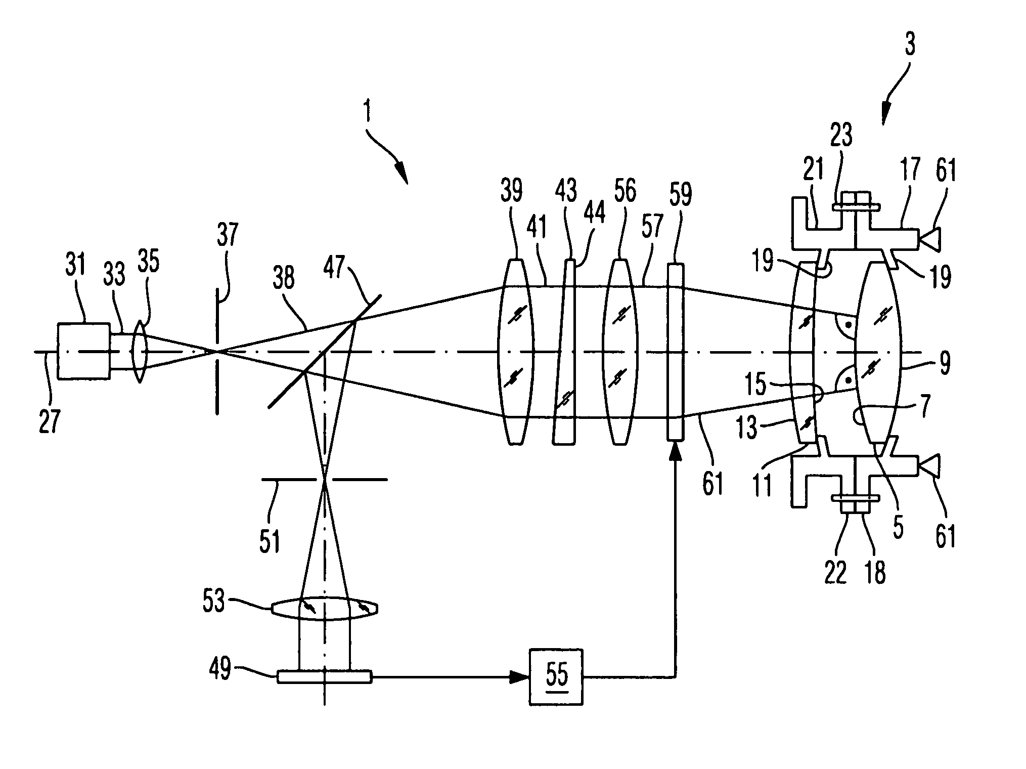
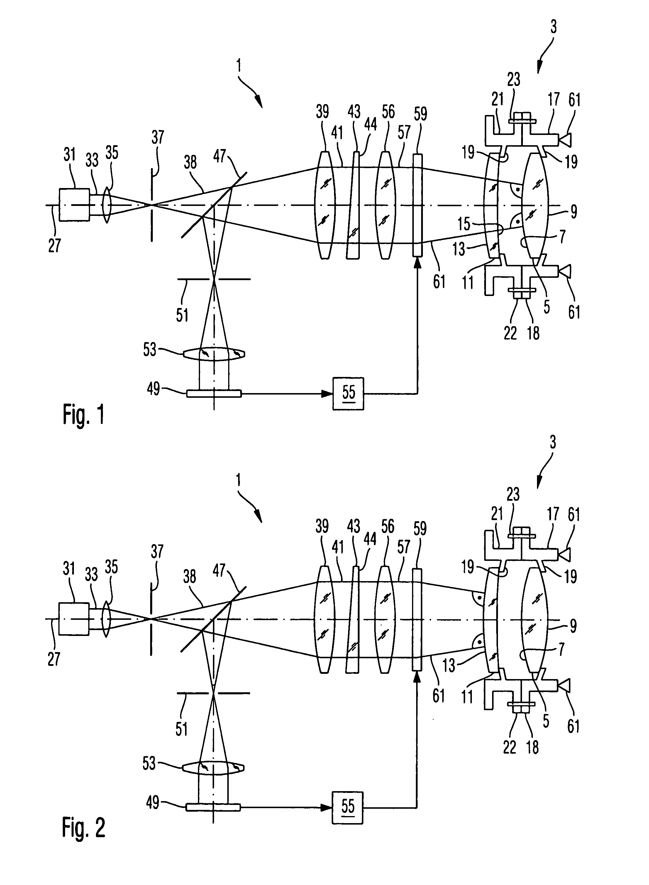
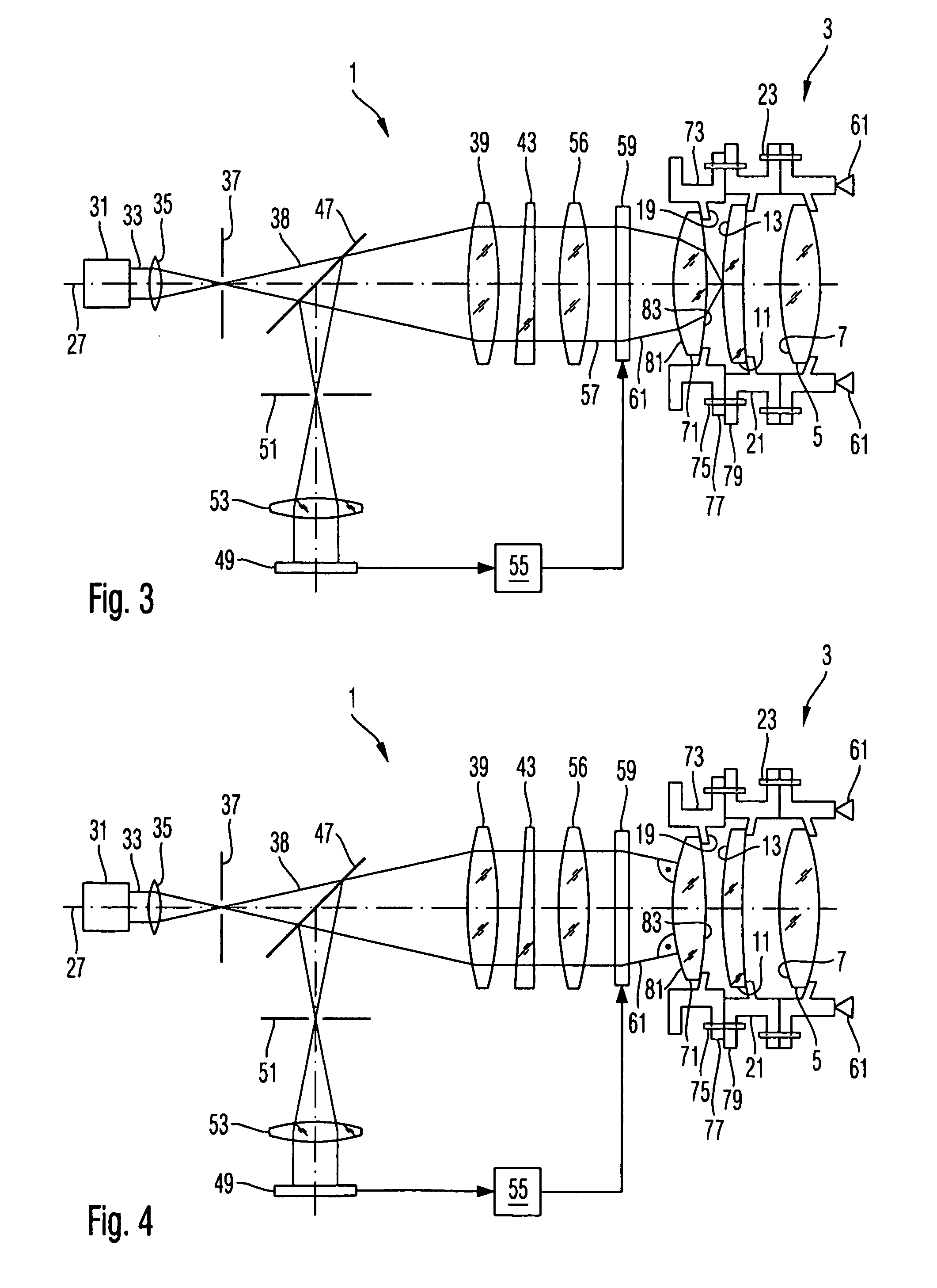
[0029]FIG. 1 schematically illustrates an interferometer apparatus 1 for testing an optical system 3. The optical system 3 comprises a first lens 5 having a front surface 7 and a back surface 9, and a second lens 11 having a front surface 13 and a back surface 15. The lens 5 is mounted on a frame 17 having plural supporting lugs 19 distributed about a circumference of the frame 17 and contacting the back surface 9 of the lens 5 at a periphery thereof.

[0030]Similarly, lens 11 is supported by supporting lugs 19 of a mounting frame 21. The supporting frame 17 has a flange 18 joined to a flange 22 of mounting frame 21 by a plurality of b...


PUM


Abstract

A method of manufacturing an optical system having plural optical elements mounted relative to each other on a mounting structure of the optical system comprises disposing the optical system in a beam path of an interferometer apparatus having an interferometer optics and a selectable hologram for shaping a beam of measuring light to be incident on surfaces of the optical elements of the optical system; selecting a first hologram of the interferometer apparatus and recording at least one first interference pattern generated by measuring light reflected from a surface of a first optical element; selecting a second hologram of the interferometer apparatus, wherein the second hologram is different from the first hologram, and recording at least one second interference pattern generated by measuring light reflected from a surface of a second optical element, which is different from the first optical element; and adjusting a position of the first optical element relative to the second optical element on the mounting structure based upon the first interference pattern and the second interference pattern.

Description

BACKGROUND OF THE INVENTION[0001]1. Field of the Invention[0002]The present invention generally relates to a method of manufacturing an optical system. In particular, the invention relates to adjusting lenses of an optical system relative to each other.[0003]2. Brief Description of Related Art[0004]Generally, a performance of an optical system is determined by a quality of its optical components, such as lenses and mirrors, comprised by the system, and by an accuracy of an alignment of the optical components relative to each other. Typically, the optical elements are made of a glass or other suitable material, and their optical surfaces are processed to have a surface shape corresponding to a specification of the optical system. Thereafter, each optical element is attached to a mounting frame made of metal or other suitable material, wherein the mounting frame provides mechanical attachment means, such as flanges, through-holes and others. Thereafter, the optical system is assembled...

Claims


Application Information

Patent Timeline
Patent Type & Authority Applications(United States)
IPC IPC(8): G01B9/021
CPCG01M11/0221G03F7/70258G02B27/62G02B5/32G01B9/02039
Inventor FREIMANN, ROLFWAGEMANN, ULRICH
Owner CARL ZEISS SMT GMBH
Why Eureka
Try Eureka