System and method for minimizing hysteresis in a motor drive system

a technology of motor drive and hysteresis, which is applied in the direction of vehicle components, lighting and heating apparatus, lighting applications, etc., can solve the problems of mechanical hysteresis or backlash in the mechanical drive system, limiting the accuracy and limiting the accuracy and repeatability of the movement of the automated luminair

Active Publication Date: 2009-09-17
ROBE LIGHTING
View PDF2 Cites 19 Cited by
  • Summary
  • Abstract
  • Description
  • Claims
  • Application Information

AI Technical Summary

Problems solved by technology

With this level of accuracy in the control instructional portion of the control system, the limiting factor in controlling the accuracy of the luminaire's motion predominantly lies with the mechanical systems used to move the pan and tilt axes.
One particular problem inhibiting and limiting the accuracy and repeatability of the movements of an automated luminaire is the mechanical hysteresis or backlash in the mechanical drive system.
In both cases there is inevitably an amount of backlash or slippage or shifting which induces hysteresis in the system.
A clockwise pan to a stop position will allow the slack in belts or tolerance in gears and mountings to accumulate on one side of the system while an counter-clockwise pan to the same stop position will accumulate that same slack and tolerance on the other side thus giving an effective positional error of approximately two time (2×) the actual slack
Such resilient dampeners are effective at reducing vibration however they introduce a further source of hysteresis due to the inherent flex of the resilient materials.
In practice such systems are difficult to control and difficult to manufacture repeatedly and consistently.
Additionally any deliberate addition of friction will of necessity increase the power and size of motors needed.
Such systems are expensive to manufacture and may require significant processing power for each motor to ensure that smooth accurate movement occurs without hunting or overshoot.
This system is slow to operate, requires an accurate sensor on the driven shaft and produces motion in the driven shaft while the final position is sought.
Any such motion would be noticeable and distracting to the audience.
This methodology has the disadvantage in that it gives significant and noticeable movement in the output not appropriate for the entertainment lighting application.
While the Misumi and Liepe systems may eventually and consistently get to the right position, the process of getting there may be worse than the hysteresis problem they solve in an automated luminaire application.
Such a system is difficult to maintain as any changes in the system due to wear and tear or replacement of parts such as belts will require re-calibration and adjustment of the compensation system.
Although this provides good control of backlash when the system is always rotating in one direction to its final position, it doesn't cope as well with a system which has no prior knowledge of that direction and that can be required to travel to the same target position from either direction interchangeably.

Method used


Image

  • System and method for minimizing hysteresis in a motor drive system
  • System and method for minimizing hysteresis in a motor drive system
  • System and method for minimizing hysteresis in a motor drive system

Examples


Embodiment Construction

[0029]Preferred embodiments of the present invention are illustrated in the FIGUREs, like numerals being used to refer to like and corresponding parts of the various drawings.

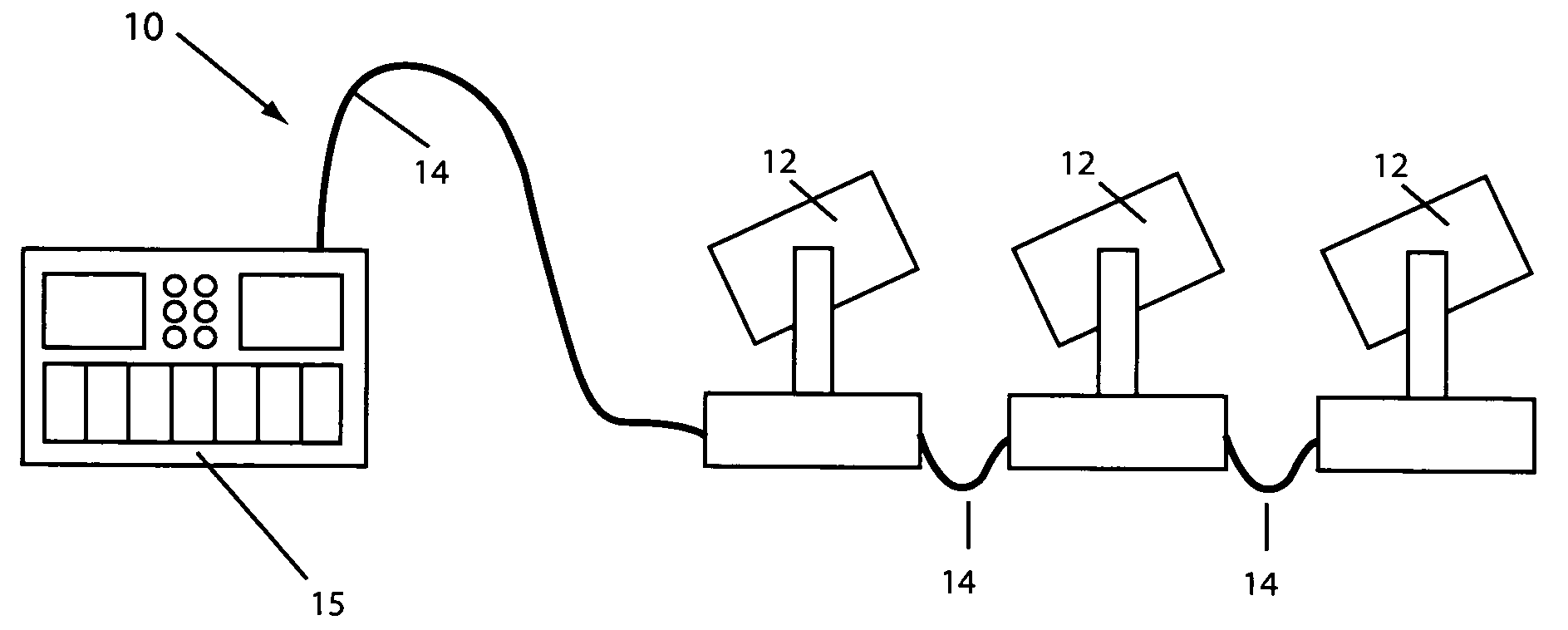
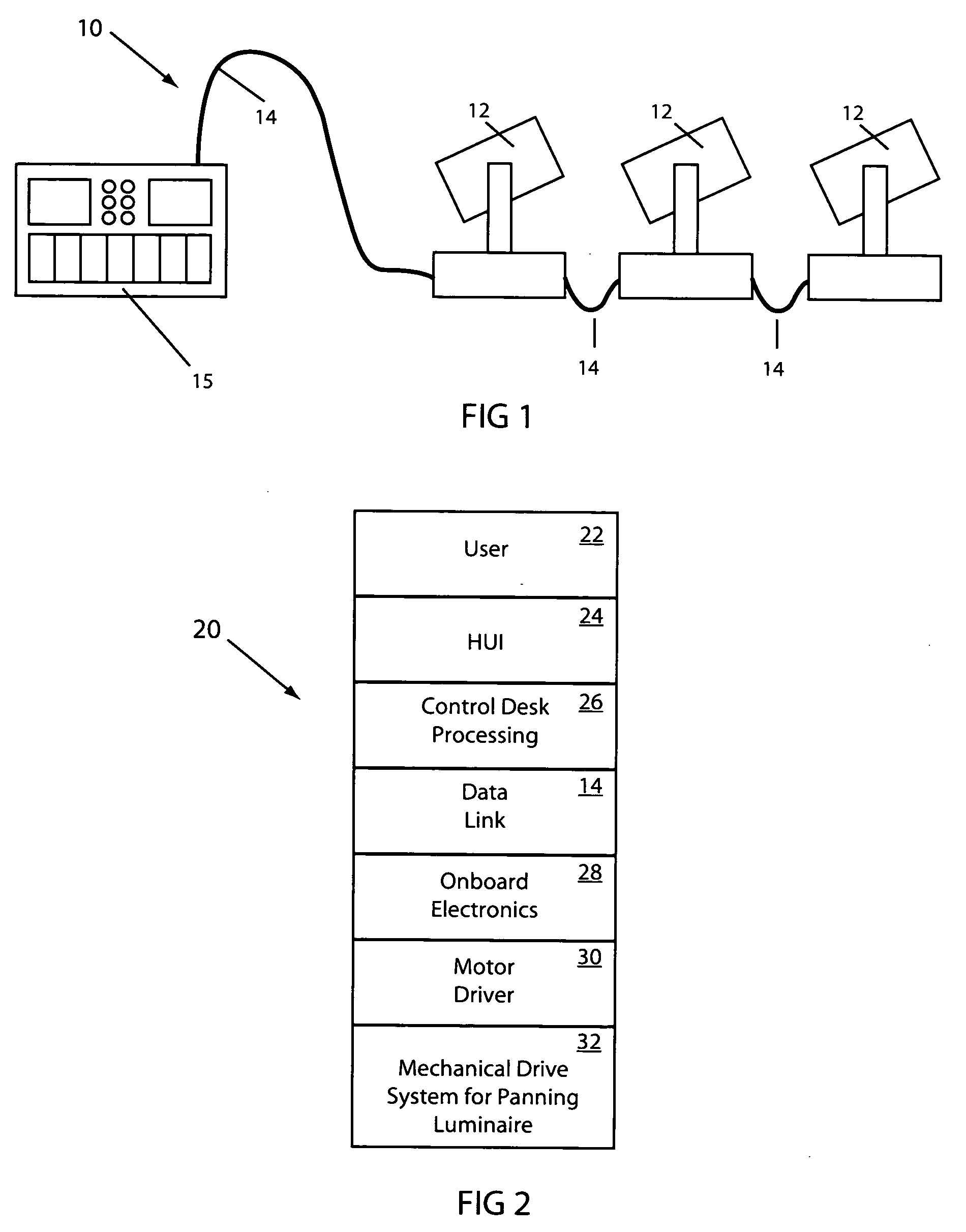
[0030]The present invention generally relates to motor control systems and specifically to the use of multiple motors to move a single output shaft in an automated luminaire. The system disclosed provides smooth movement and reduces backlash in the movement to provide a system with high positional accuracy while mitigating the need for expensive high resolution encoders.

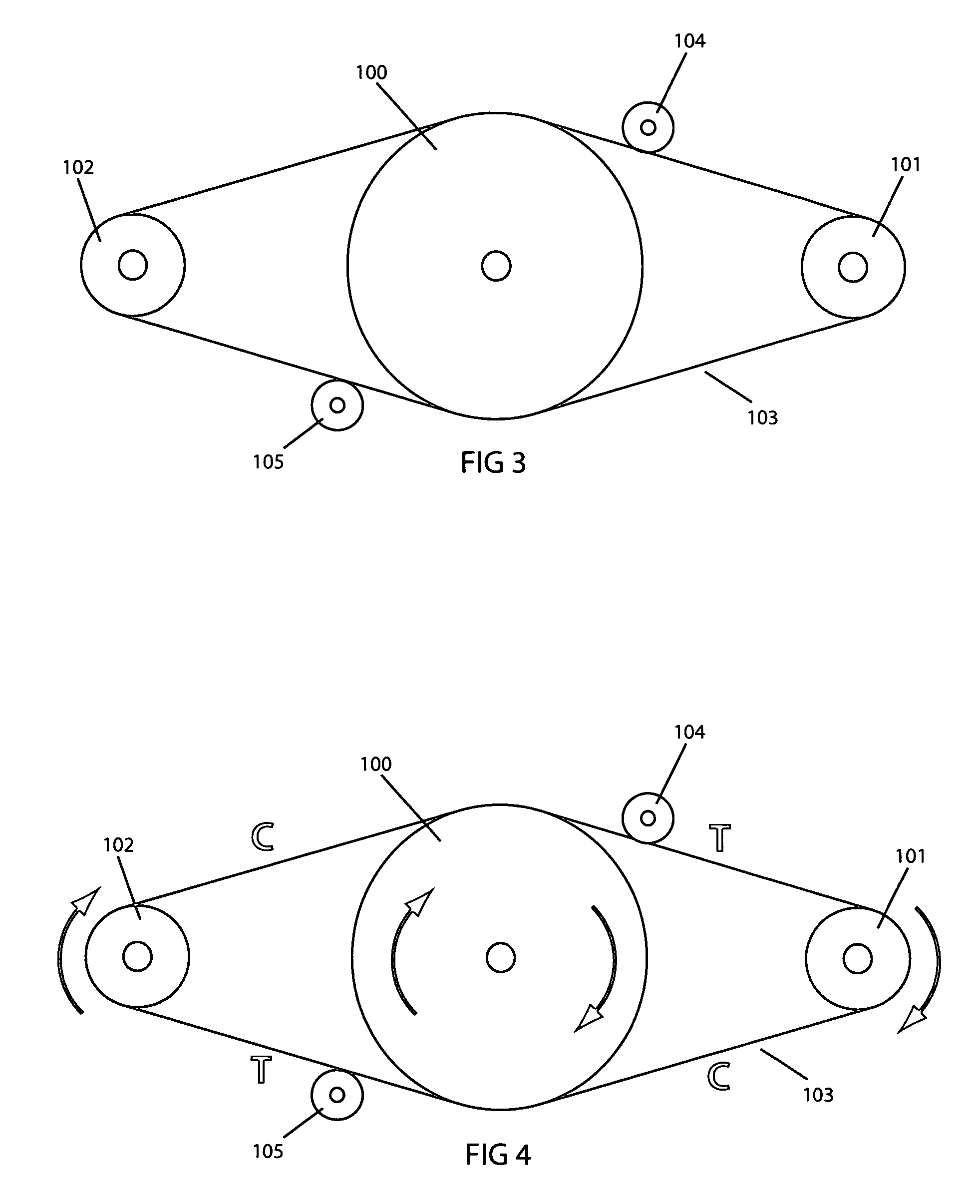
[0031]In one embodiment the present invention utilizes two motors driving a single output shaft through common or separate drive trains. After the control system detects that the system has come to rest the unit relaxes and equalizes the slack and / or tension in the drive train by first rotating the two motors as an antagonistic pair in opposing directions in one rotation direction, then reversing this turn by rotating the two motors as an antago...


PUM


Abstract

The present invention provides an automated luminaire with more repeatable, identical and accurate movements by normalization for motion drive system hysteresis. The normalization system utilizes the use of multiple drivers which drive the drive system which engage in opposing movements following a movement to normalize the hysteresis in the drive system so that subsequent moves begin from the same drive system conditions.

Description

TECHNICAL FIELD OF THE INVENTION[0001]The present invention generally relates to motor drive systems and more specifically to the configuration and control of motors and drive systems to move an output shaft in an automated multiparameter luminaire.BACKGROUND OF THE INVENTION[0002]Luminaries with automated and remotely controllable functionality are well known in the entertainment and architectural lighting markets. Such products are commonly used in theatres, television studios, concerts, theme parks, night clubs and other venues. A typical product will typically provide control over the pan and tilt functions of the luminaire allowing the operator to control the direction the luminaire is pointing and thus the position of the light beam on the stage or in the studio. Typically this position control is done via control of the luminaire's position in two orthogonal rotational axes usually referred to as pan and tilt. Many products provide control over other parameters such as the in...

Claims


Application Information

Patent Timeline
Patent Type & Authority Applications(United States)
IPC IPC(8): F21V21/15
CPCG05B19/404G05B2219/41264G05B2219/41034F21V21/15F21V21/30F21W2131/406
Inventor POLASEK, JIRI
Owner ROBE LIGHTING
Why Eureka
Try Eureka