Programming method and memory device using the same

Active Publication Date: 2009-09-17
MACRONIX INT CO LTD
View PDF2 Cites 0 Cited by
  • Summary
  • Abstract
  • Description
  • Claims
  • Application Information

AI Technical Summary

Benefits of technology

[0008]The invention is directed to a programming method and a memory device using the same, wherein two programming operations are executed so that a margin of the threshold voltage distribution of a memory array is narrowed and the data reading correctness can be enhanced.

Problems solved by technology

Because the threshold voltage distribution influences the operation of reading the memory cell, a read error tends to occur if the margin of the threshold voltage distribution of the threshold voltage represented by the threshold voltage state becomes wider.

Method used


Image

  • Programming method and memory device using the same
  • Programming method and memory device using the same
  • Programming method and memory device using the same

Examples


Embodiment Construction

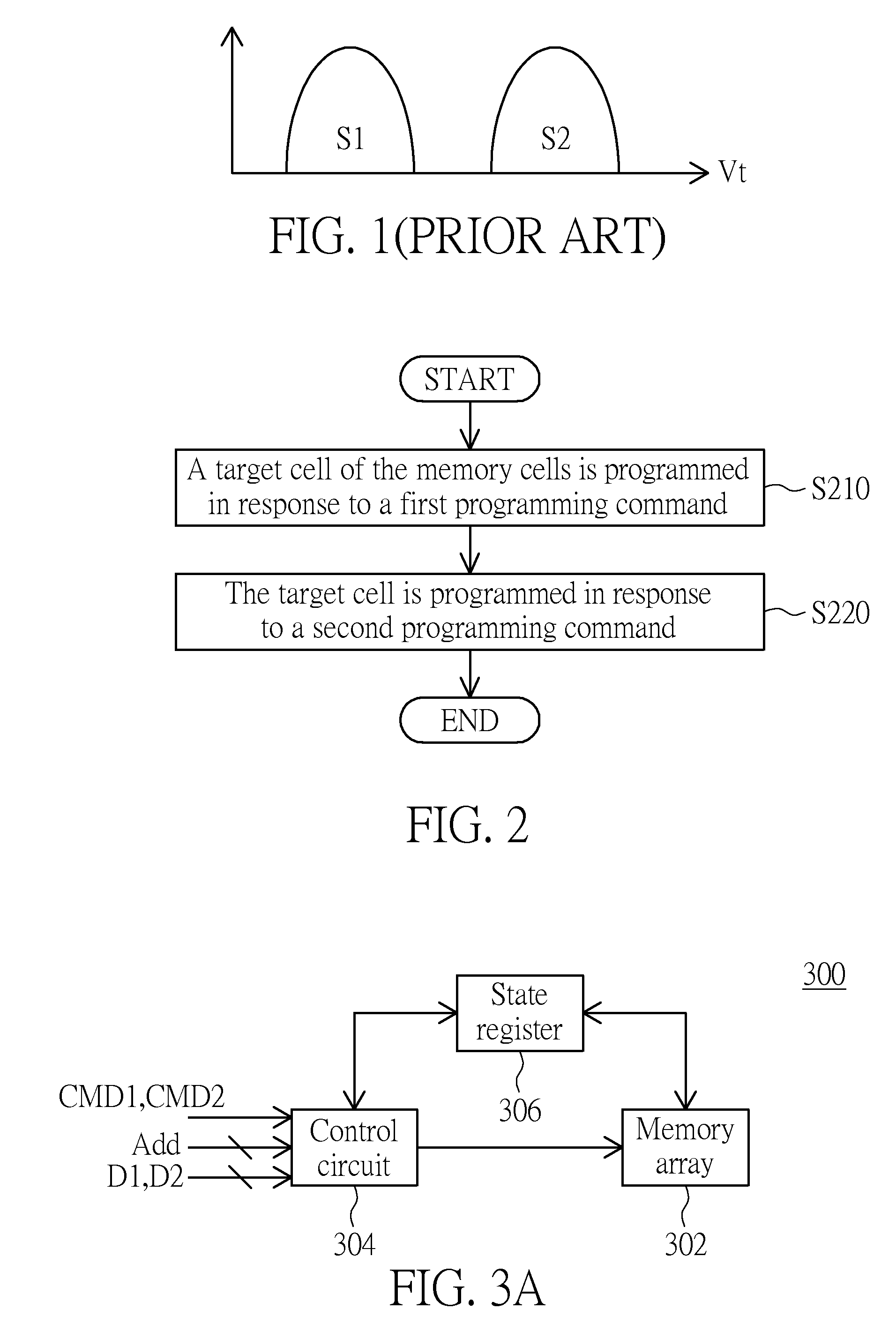
[0022]FIG. 2 is a flow chart showing a programming method according to an embodiment of the invention. The programming method according to this invention is applied to a memory having many memory cells. The method includes the following steps. In step S210, a target cell of the memory cells is programmed in response to a first programming command. In step S220, the target cell is programmed in response to a second programming command.

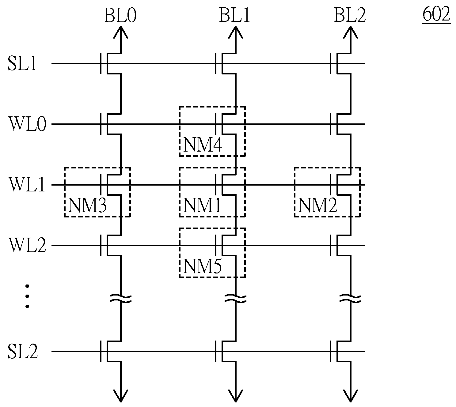
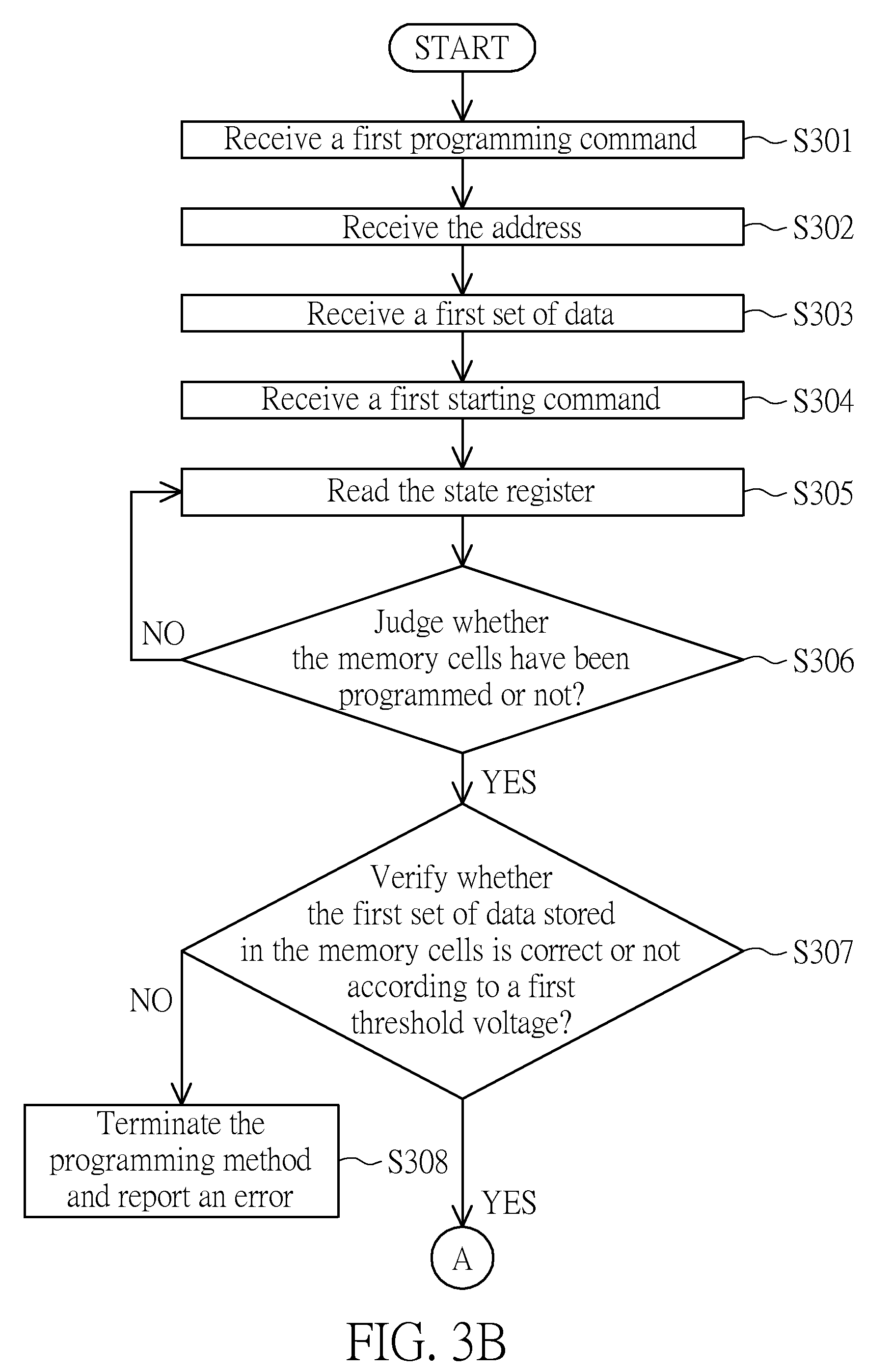
[0023]How the memory device executes the programming method will be further described in detail in the following. FIG. 3A is a schematic illustration showing a memory device 300 according to an embodiment of the invention. FIGS. 3B and 3C are a detailed flow chart showing the programming method executed by the memory device of FIG. 3A. Referring to FIGS. 3A-3C, the memory device 300 includes a memory array 302, a control circuit 304 and a state register 306. The memory array 302 has many memory cells M each having its address.

[0024]The control circuit 3...


PUM


Abstract

A programming method applied to a memory is provided. The memory includes a number of memory cells. The method includes the following steps. A target cell of the memory cells is programmed in response to a first programming command. The target cell is programmed in response to a second programming command.

Description

[0001]This application claims the benefit of U.S. provisional application Ser. No. 61 / 035,750, filed Mar. 12, 2008, the subject matter of which is incorporated herein by reference.BACKGROUND OF THE INVENTION[0002]1. Field of the Invention[0003]The invention relates in general to a programming method and a memory device using the same, and more particularly to a programming method capable of making a threshold voltage more precise, and a memory device using the same.[0004]2. Description of the Related Art[0005]Non-volatile memories are widely applied to various products, such as mobile phones, digital cameras or personal digital assistants (PDAs). The non-volatile memories may be classified into many types, one of which is a flash memory that is frequently seen.[0006]A memory array has many memory cells for trapping charges. The trapped charges influence the state of the threshold voltage of each memory cell so that the object of storing data can be achieved. That is, the stored data...

Claims


Application Information

Patent Timeline
IPC IPC(8): G11C16/06G11C7/00
CPCG11C16/3454G11C16/3404
Inventor HUNG, CHUN-HSIUNGHO, HSIN-YI
Owner MACRONIX INT CO LTD
Why Eureka
Try Eureka