Information processing system, tunnel communication device, tunnell communication method, proxy response device, and proxy response method

Active Publication Date: 2009-09-17
PANASONIC CORP
View PDF15 Cites 36 Cited by
  • Summary
  • Abstract
  • Description
  • Claims
  • Application Information

AI Technical Summary

Benefits of technology

[0068]According to this configuration, the second information processing device is connected to the local side of the second tunnel communication device. Accordingly, it is possible to easily distinguish the packet transmitted from the second information processing device and the packet transmitted from the second tunnel communication device from each other. In this case, the second tunnel communication device can satisfactorily receive the packet transmitted from the second information processing device.
[0069]The information

Problems solved by technology

However, a complex setup for a device serving as a connection point such as a router is required to connect plural local are

Method used


Image

  • Information processing system, tunnel communication device, tunnell communication method, proxy response device, and proxy response method
  • Information processing system, tunnel communication device, tunnell communication method, proxy response device, and proxy response method
  • Information processing system, tunnel communication device, tunnell communication method, proxy response device, and proxy response method

Examples


Example

First Embodiment

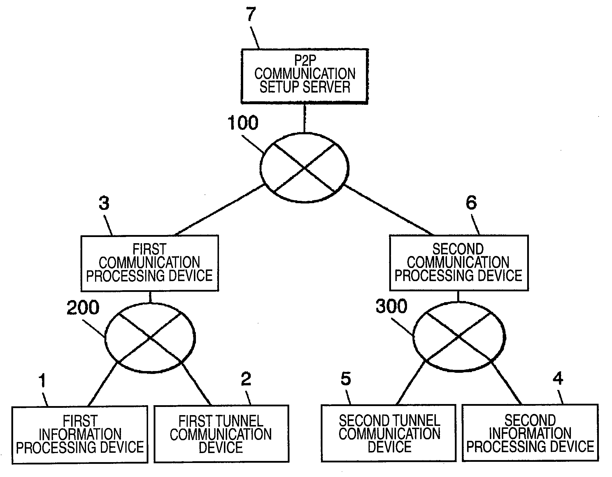
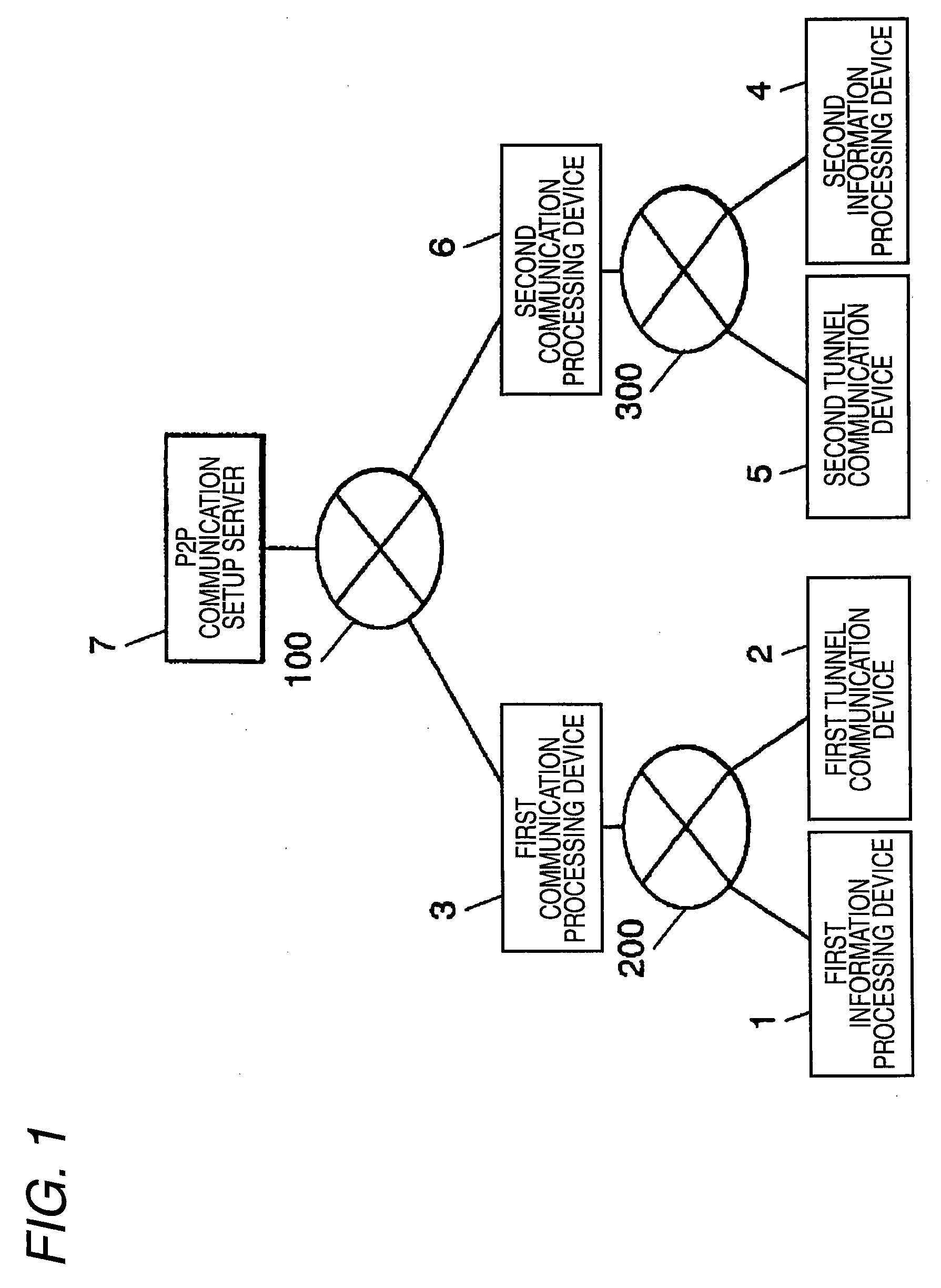
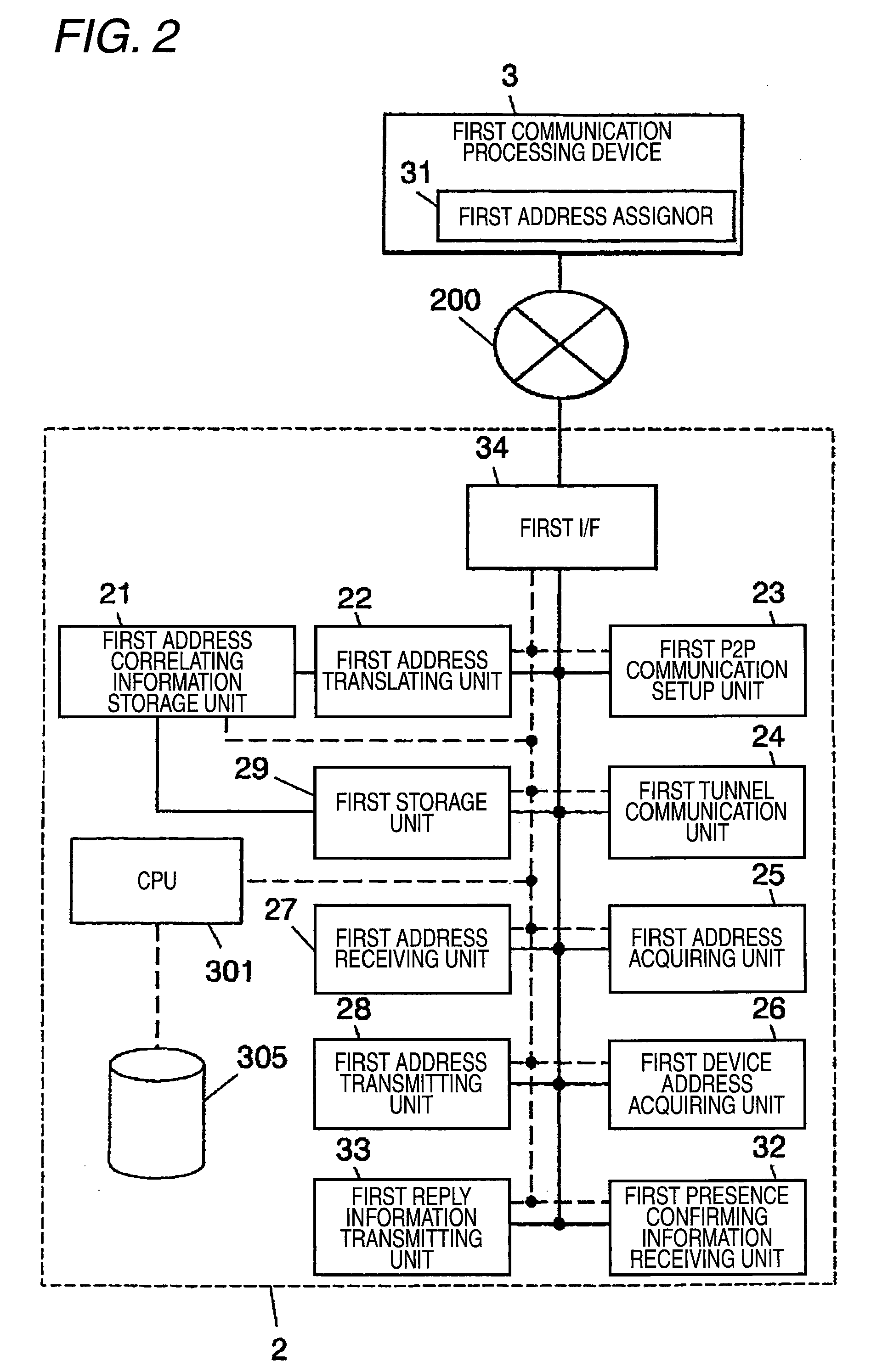
[0159]FIG. 1 is a block diagram illustrating a configuration of an information processing system according to a first embodiment of the invention. FIG. 2 is a diagram illustrating a part of the configuration of the information processing system, which includes a block diagram illustrating a first tunnel communication device according to the first embodiment. FIG. 3 is a diagram illustrating a part of the configuration of the information processing system, which includes a block diagram illustrating a second tunnel communication device according to the first embodiment. FIG. 4 is a flowchart illustrating an operation of the first tunnel communication device according to the first embodiment. FIG. 5 is a flowchart illustrating an operation of the second tunnel communication device according to the first embodiment. FIG. 6 is a diagram illustrating an address translating operation of the information processing system according to the first embodiment.

[0160]FIG. 7 is a d...

Example

[0229]Specific Example 1 of this embodiment is described now.

[0230]Pattern (A) of FIG. 7 is described in this specific example. As can be seen from FIG. 7, in this specific example, when a packet is transmitted from the first information processing device 1 to the second information processing device 4, the destination address and the source address are translated by the first address translating unit 22. When a packet is transmitted from the second information processing device 4 to the first information processing device 1, the destination address and the source address are translated by the second address translating unit 52.

[0231]Accordingly, the first address correlating information includes information for correlating the address of the first information processing device 1 in the first LAN 200 with the address of the first information processing device 11 the second LAN 300. The first address correlating information includes information for correlating the address of the seco...

Example

[0332]Specific Example 3 of this embodiment is described now. In this specific example, pattern (B) of FIG. 7 is described. As can be seen from FIG. 7, in this specific example, when a packet is transmitted from the first information processing device 1 to the second information processing device 4, the source address is translated by the first address translating unit 22. The destination address is translated by the second address translating unit 52. When a packet is transmitted from the second information processing device 4 to the first information processing device 1, the source address is translated by the first address translating unit 22. The destination address is translated by the second address translating unit 52.

[0333]Accordingly, the first address correlating information includes the information for correlating the address of the first information processing device 1 in the first LAN 200 with the address of the first information processing device 1 in the second LAN 30...


PUM


Abstract

Provided is an information processing system and the like that can make a communication between plural information processing devices belonging to different LANs. A first tunnel communication device includes a first address correlating information memory unit that stores information for correlating an address in a first LAN with an address in a second LAN, a first address translating unit that translates an address of a packet on the basis of the correlating information, a first P2P communication setup unit that sets up a P2P communication with a device as a destination, and a first tunnel communication unit that makes a tunnel communication through a path of a P2P communication. The packet transmitted from a first information processing device is translated in address, is encapsulated, and is then transmitted through the path of the P2P communication. The packet transmitted from the device as a destination is decapsulated, is translated in address, and is then transmitted to the first information processing device.

Description

TECHNICAL FIELD[0001]The present invention relates to an information processing system, a tunnel communication device, a tunnel communication method, a proxy response device, and a proxy response method, for encapsulating a packet to make a tunnel communication.BACKGROUND ART[0002]Conventionally, information processing systems use a technology of a virtual private network (hereinafter, referred to as “VPN). Plural points connected to a communication line such as Internet could communicate with each other as if they are connected to each other through an exclusive line, by using the technology. This configuration is disclosed in Charlie Scott's Document (“Virtual Private Networks, Second Edition” written by Charlie Scott, Paul Wolfe, and Mike Erwin, O'REILLY, December of 1998, P1˜9 and P11 to 22).[0003]However, a complex setup for a device serving as a connection point such as a router is required to connect plural local area networks. A user should make such a setup. Therefore, if t...

Claims


Application Information

Patent Timeline
IPC IPC(8): H04L12/56H04L12/701H04L12/70
CPCH04L12/66H04L12/4633
Inventor GOBARA, KUNIOMAEKAWA, HAJIMEMATSUMOTO, KENICHIKOYAMA, MASANOBU
Owner PANASONIC CORP
Why Eureka
Try Eureka