Ripcord of optic cables and method of manufacturing the same

Inactive Publication Date: 2010-05-27
KOLON IND INC
View PDF12 Cites 1 Cited by
  • Summary
  • Abstract
  • Description
  • Claims
  • Application Information

AI Technical Summary

Benefits of technology

[0051]A ripcord for optic cable according to the present invention has a coating layer containing a colorant on a surface of a folded and twisted yarn formed by folding and twisting together wholly aromatic polyamide filaments, so as to easily distinguish the ripcord from reinforcing materials of the optic cable at installation and repairs of the optic cable and have excellent mechanical properties such as high strength owing to inherent properties of the wholly aromatic polyamide filaments.
[0052]Especially, the inventive ripcord which has a coating layer containing fluorescent ingredients can be simply distinguished from the reinforcing materials of the optic cable even in a dark place such as a tunnel.
[0053]The p

Problems solved by technology

However, since such ripcord comprises the wholly aromatic polyamide filaments only, this has disadvantages including, for example, poor dyeing properties, reduced dyeing intensity, low dyeing fastness, high production cost, etc. in spite of excellent mechanical properties such as modulus.
Especially, the known ripcord 3 for optic cable with poor dyeing properties and dyeing fastness involved a problem that the ripcord is difficult to distinguish from the reinforcing material 2 of the optic cable during repairing.
However, when comparing it with a ripcord formed of wholly aromatic polyamide fibers, this ripcord needs higher denier and larger weight to have desired mechanical

Method used


Image

  • Ripcord of optic cables and method of manufacturing the same
  • Ripcord of optic cables and method of manufacturing the same

Examples


Example

Example 1

[0061]A folded and twisted yarn A with total fineness of 3,000 denier was prepared, which consisted of two strands of wholly aromatic polyamide filament each comprising 1,000 mono filaments with mono fineness of 1.5 denier.

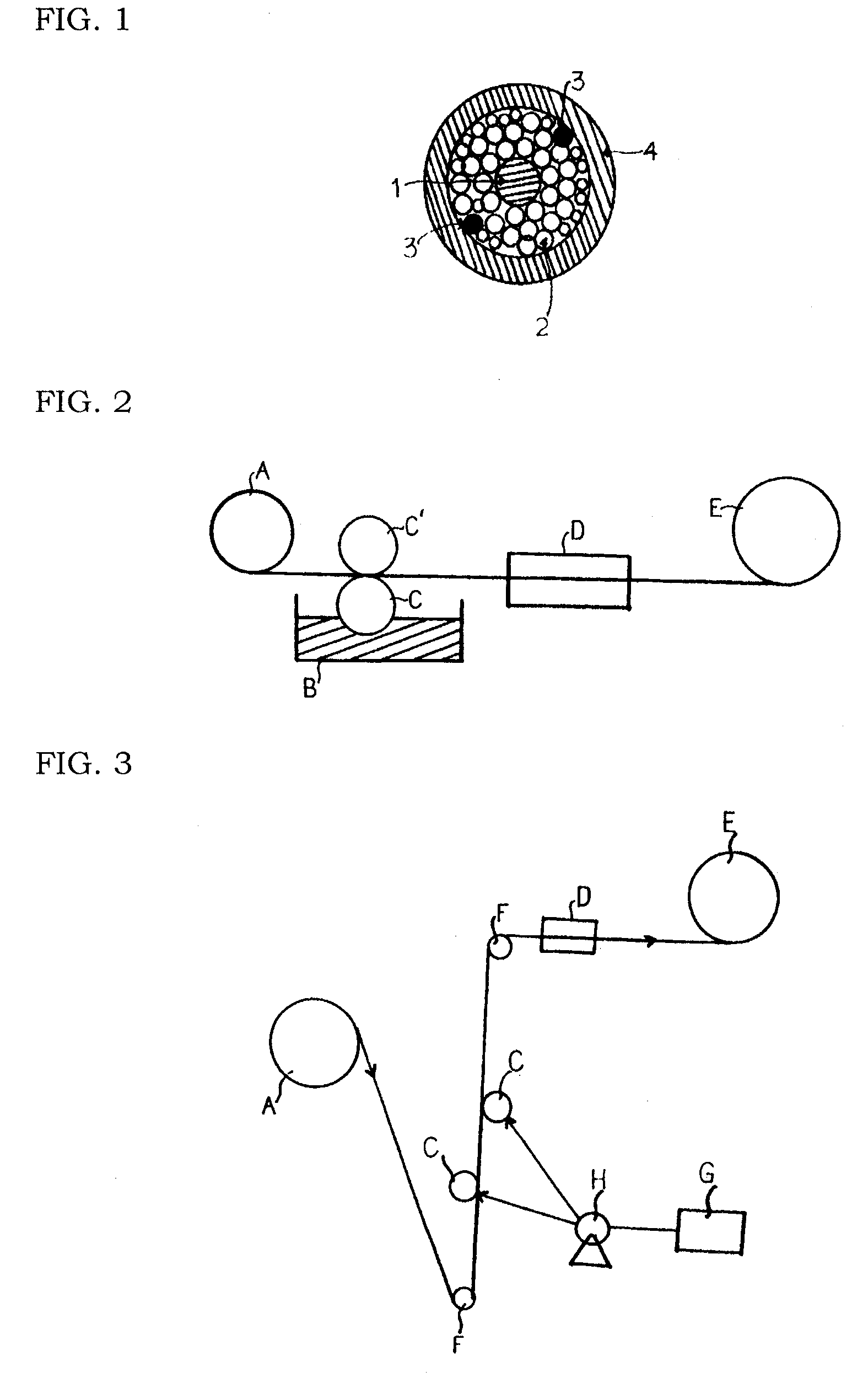
[0062]As shown in FIG. 2, the prepared folded and twisted yarn was passed over a rotational coating roller C that was partially immersed in a tank B containing a coating solution which included (i) a polyethyleneglycol binder having a number average molecular weight of 400 and (ii) a colorant having an average particle size of 5 μm dispersed in the binder to apply the coating solution to a surface of the folded and twisted yarn A to form a coating layer. Following this, the coated yarn was wound over a winder E to produce a ripcord 3 for optic cable.

[0063]The coating roller C was equipped with a squeezing roller C′ at the top of the roller C.

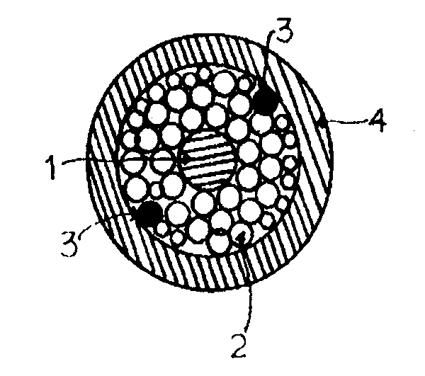
[0064]After covering an optic fiber 1 with the produced ripcord 3 together with a reinforcing material 2 made of a ...

Example

Example 2

[0066]A folded and twisted yarn A with total fineness of 4,500 denier was prepared, which consisted of three strands of wholly aromatic polyamide filament each comprising 1,000 mono filaments with mono fineness of 1.5 denier.

[0067]As shown in FIG. 3, the prepared folded and twisted yarn was passed over a coating roller C fed with a coating solution which included (i) a polytetramethyleneglycol binder having a number average molecular weight of 600 and (ii) a colorant having an average particle size of 5 μm dispersed in the binder, from a tank B containing the coating solution by means of an injector H to apply the coating solution to a surface of the folded and twisted yarn A to form a coating layer. Following this, the coated yarn was wound over a winder E to produce a ripcord 3 for optic cable.

[0068]After covering an optic fiber 1 with the produced ripcord 3 together with a reinforcing material 2 made of a folded and twisted yarn comprising wholly aromatic polyamide filam...

Example

Example 3

[0070]A ripcord for optic cable and an optic cable with a cross section shown in FIG. 1 were produced under the same conditions described in Example 1 except that an alternative coating solution which included (i) an aqueous acrylic resin binder, (ii) a pigment having an average particle size of 5 μm dispersed in the binder and (iii) water as a diluent was used instead of the coating solution described in Example 1 and, after applying the coating solution to a surface of the folded and twisted yarn A to form a coating layer, the coated yarn was first passed through a dryer D at 200° C. with a speed of 20 m / min before winding the yarn over a winder E.

[0071]Strength of the ripcord and convenience in distinguishing the ripcord from the optic cable were evaluated and the results are shown in the following Table 1.


PUM

PropertyMeasurementUnit
Temperatureaaaaaaaaaa
Linear densityaaaaaaaaaa
Forceaaaaaaaaaa

Abstract

Disclosed are a ripcord for optic cable and a method of manufacturing the same. The ripcord for optic cable has a coating layer formed by applying a coating solution, which includes a binder and a colorant dispersed in the binder, to a surface of a folded and twisted yarn formed by folding and twisting together wholly aromatic polyamide filaments.

Description

TECHNICAL FIELD[0001]The present invention relates to a ripcord for optic cables and a method of manufacturing the same, and more particularly, to a ripcord for optic cable which comprises a folded and twisted yarn formed by folding and twisting together wholly aromatic polyamide filaments and a coating layer containing a coloring agent formed on a surface of the folded and twisted yarn, so that the ripcord can be easily distinguished from reinforcing materials for the optic cable at installation or repairs of the optic cable, thereby enhancing workability thereof and, in addition, a method of manufacturing the same.BACKGROUND ART[0002]A ripcord for optic cable is so called “a cutting fiber,” which helps a resin coating film of an optic cable to be easily cut and removed.[0003]As shown in FIG. 1, the optic cable generally includes an optic fiber 1 at a center of the optic cable, a reinforcing material 2 covering and protecting the optic fiber 1, ripcords 3 mixed in the reinforcing m...

Claims


Application Information

Patent Timeline
IPC IPC(8): D02G3/36D02G3/26B05D3/12
CPCG02B6/4495Y10T428/2927Y10T428/2936G02B6/4431
Inventor LEE, CHANG-BAEPARK, TAE-HAKKIM
Owner KOLON IND INC
Why Eureka
Try Eureka