
Image prediction encoding device, image prediction decoding device, image prediction encoding method, image prediction decoding method, image prediction encoding program, and image prediction decoding program

a technology of image prediction and decoding method, applied in signal generators with optical-mechanical scanning, color television with bandwidth reduction, etc., can solve the problems of inability to adequately suppress the bit amount of mode information, inability to generate reference mode information at high accuracy with respect to the optimum prediction method (of the target block), etc., to achieve efficient encoding processing and reduce the effect of predictive method-related mode information

Inactive Publication Date: 2009-09-17
NTT DOCOMO INC
View PDF7 Cites 44 Cited by
  • Summary
  • Abstract
  • Description
  • Claims
  • Application Information

AI Technical Summary

Benefits of technology

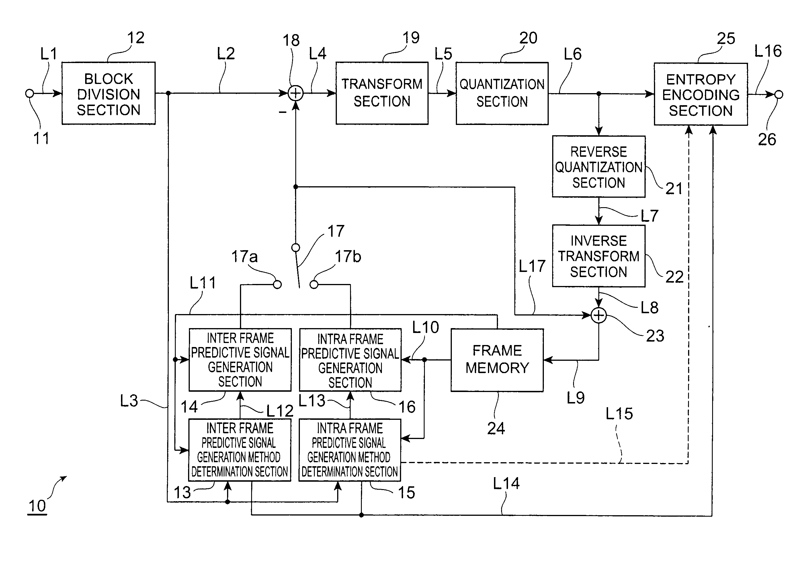
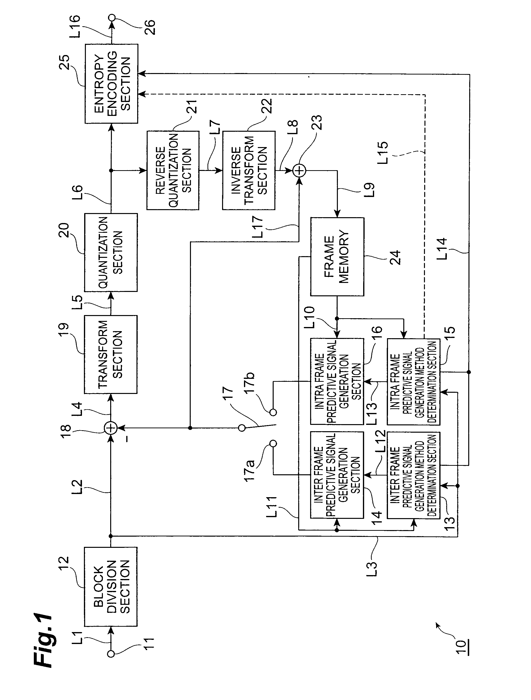
The present invention provides an image prediction encoding device and method that reduces the amount of mode information needed to identify the predictive method, and improves the efficiency of encoding pixel signals. The device divides the image into multiple areas, generates an intra frame predictive signal for each area, and encodes the residual signal between the pixel signals of the target area and the intra frame predictive signal. The method derives a predictive method for generating the intra frame predictive signal based on processed data from adjacent areas, resulting in improved encoding efficiency.

Problems solved by technology

However, as a result of using two adjacent blocks, there is a tendency for the generation of reference mode information at high accuracy with respect to the optimum predictive method (of the target block) to be impossible and it is not possible to adequately suppress the bit amount of the mode information.

Method used


Image

  • Image prediction encoding device, image prediction decoding device, image prediction encoding method, image prediction decoding method, image prediction encoding program, and image prediction decoding program
  • Image prediction encoding device, image prediction decoding device, image prediction encoding method, image prediction decoding method, image prediction encoding program, and image prediction decoding program
  • Image prediction encoding device, image prediction decoding device, image prediction encoding method, image prediction decoding method, image prediction encoding program, and image prediction decoding program

Examples


Embodiment Construction

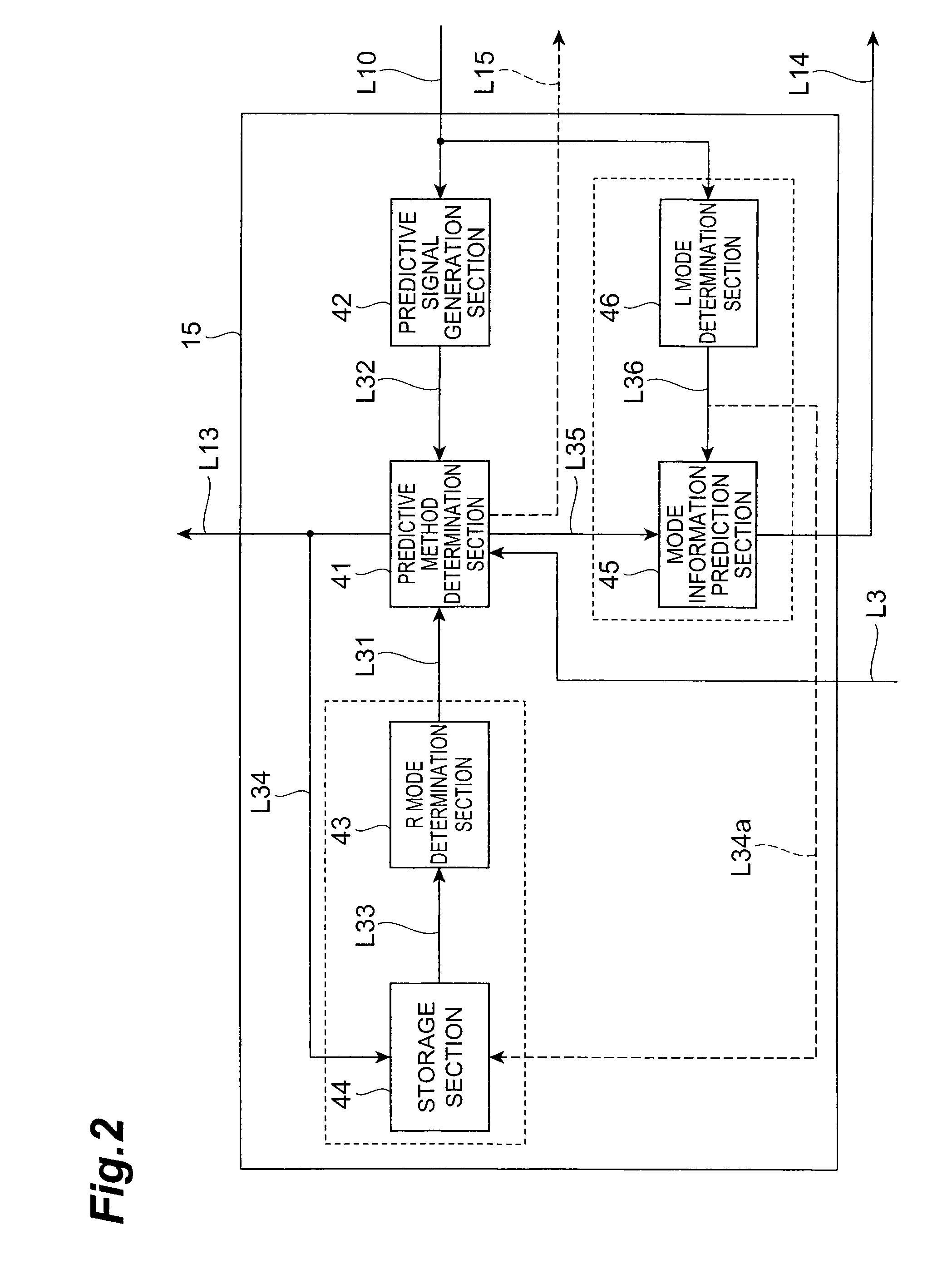
, 46 . . . L MODE DETERMINATION SECTION, 50 . . . IMAGE PREDICTIVE DECODING DEVICE, 51 . . . DATA ANALYSIS SECTION, 52 . . . REVERSE QUANTIZATION SECTION, 53 . . . INVERSE TRANSFORM SECTION, 54 . . . ADDER, 55 . . . PREDICTIVE SIGNAL GENERATION SECTION, 56 . . . FRAME MEMORY, 57 . . . PREDICTIVE METHOD ACQUISITION SECTION, 58 . . . INPUT TERMINAL, 59 . . . OUTPUT TERMINAL, 61 . . . SWITCHING SWITCH, 64 . . . R MODE DETERMINATION SECTION, 65 . . . STORAGE SECTION, 66 . . . L MODE DETERMINATION SECTION, 67 . . . MODE INFORMATION GENERATION SECTION, 115 . . . INTRA FRAME PREDICTIVE SIGNAL GENERATION METHOD DETERMINATION SECTION, 143 . . . F MODE DETERMINATION SECTION, 157 . . . PREDICTIVE METHOD ACQUISITION SECTION, 164 . . . F MODE INFORMATION STORAGE SECTION, 301, 401, 901, . . . TARGET AREA, 302a to 302f, 303a to 303c, 402 to 406, and 902 to 904 . . . ADJACENT AREA.

BEST MODE FOR CARRYING OUT THE INVENTION

[0047]Preferred embodiments of the image prediction encoding device and image p...


PUM


Abstract

An image predictive encoding device including an intra frame predictive signal generation method determination section that determines, for adjacent areas including regenerated pixel signals and adjacent to the target area, a predictive method derived on the basis of data corresponding to the adjacent areas as an R mode predictive method or an L mode predictive method, an intra frame predictive signal generation section that generates an intra frame predictive signal on the basis of the R mode predictive method thus determined, and a subtractor, a transform section, a quantization section, and an entropy encoding section that encode a residual signal of a pixel signal of the target area on the basis of the generated intra frame predictive signal.

Description

TECHNICAL FIELD[0001]The present invention relates to an image prediction encoding device, an image prediction decoding device, an image prediction encoding method, an image prediction decoding method, an image prediction encoding program, and an image prediction decoding program.BACKGROUND ART[0002]Compression is conventionally carried out by using compression encoding technology to compress image data in order to efficiently transmit and store still image data and moving image data and so forth. The MPEG1 to MPEG4 and H.261 to H.264 systems and so forth are widely used as such compression encoding technology for moving images.[0003]With such encoding systems, encoding processing and decoding processing are carried out after dividing image data constituting the encoding target into a plurality of blocks. Furthermore, in the case of the MPEG4 and H.264 systems, when encoding a target block of an intra frame in order to further raise the encoding efficiency, a predictive signal is ge...

Claims


Application Information

Patent Timeline
Patent Type & Authority Applications(United States)
IPC IPC(8): H04N7/32H04N19/50H04N19/103H04N19/11H04N19/134H04N19/136H04N19/137H04N19/182H04N19/196H04N19/463H04N19/51H04N19/593H04N19/60H04N19/61H04N19/70H04N19/91
CPCH04N19/00569H04N19/50H04N19/176H04N19/46H04N19/157H04N19/593H04N19/11H04N19/136H04N19/14H04N19/61H04N19/159H04N19/44H04N19/13H04N19/172H04N19/182
Inventor BOON, CHOONG SENGTAN, THIOW KENG
Owner NTT DOCOMO INC
Learn More