
Method and apparatus for processing an image

a processing method and image technology, applied in the field of automatic image identification, can solve the problems of high cost, limited to the detection of road signs, and large amount of data, and achieve the effect of low error probability

Inactive Publication Date: 2009-09-17
CROSS GEOFFREY MARK TIMOTHY
View PDF5 Cites 78 Cited by
  • Summary
  • Abstract
  • Description
  • Claims
  • Application Information

AI Technical Summary

Benefits of technology

[0009]It is a further object of the present invention to provide an efficient fast image processing method with low error probability for rapidly scrutinizing a digitized video image frame and processing said image frame to detect and characterise features of interest while ignoring other features of said image frame.
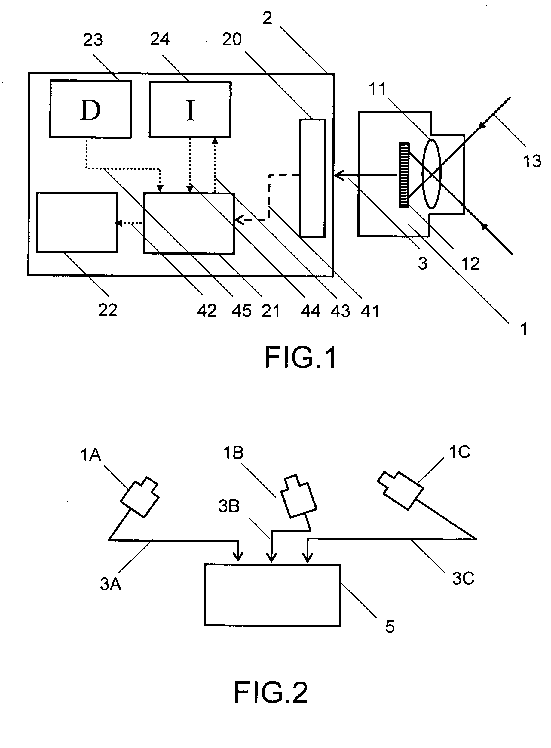
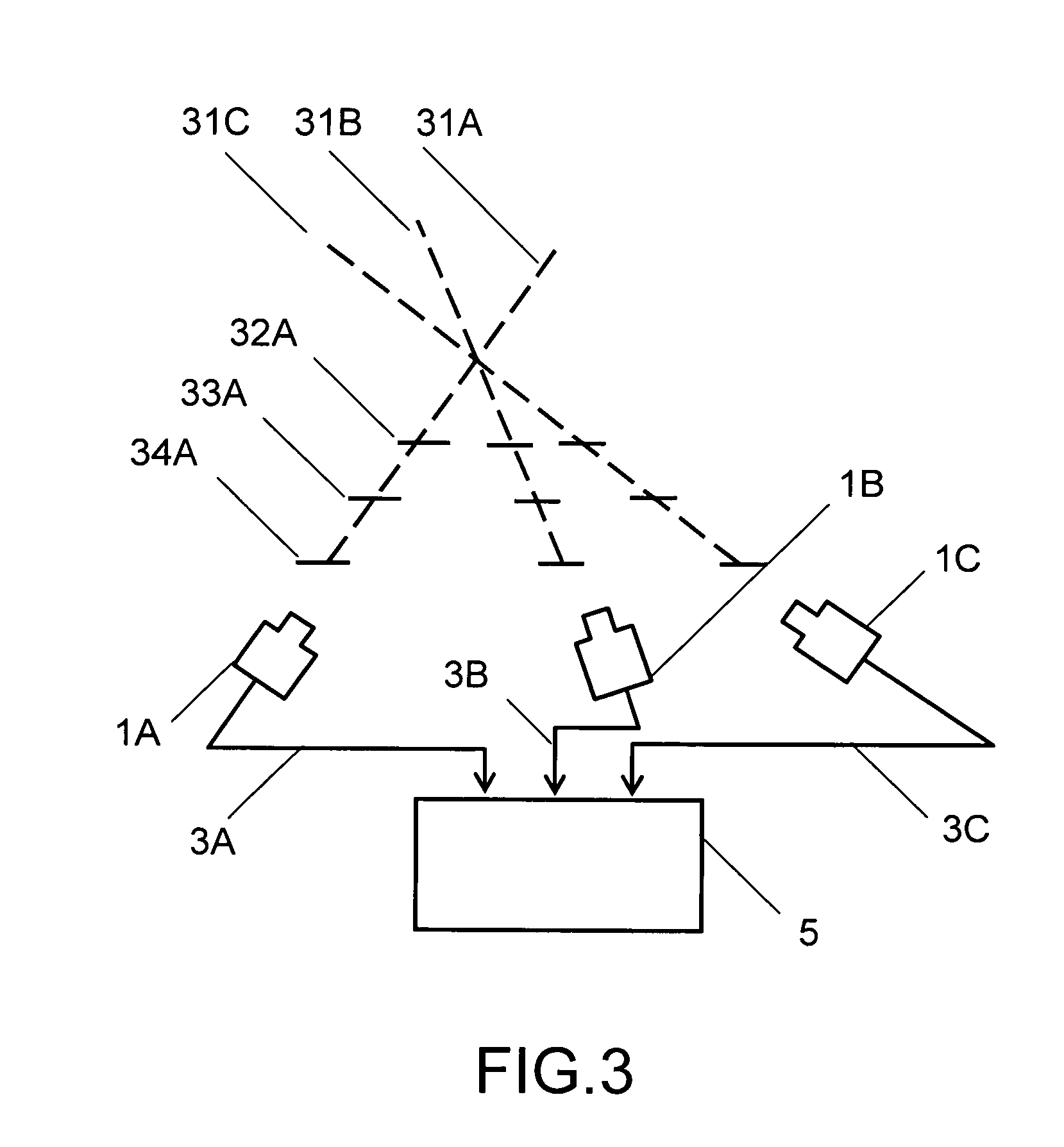
[0011]In the most basic operational embodiment of the present invention, a vehicle-mounted single imaging device is directed toward the roadside. However, more efficient implementations would comprise several imaging devices wherein each overlaps other camera(s) and is directed toward a different field of view. The use of more than imaging device allows the use of well-known techniques of triangulation.

Problems solved by technology

Such approaches suffer from the problems of optical and mechanical complexity and high cost.
This system requires specific templates of real-world features and does not operate on unknown video data.
However, the 548' patent does have the limitation that in any frame some differentiable feature (“sign-ness”) must exist in order for the frame to be retained for further analysis.
The method disclosed in the 548' patent is limited to the detection of road signs and suffers from the need to process vast amounts of data.
The prior art suffers from the problems of high error probability and processing inefficiency.

Method used


Image

  • Method and apparatus for processing an image
  • Method and apparatus for processing an image
  • Method and apparatus for processing an image

Examples


Embodiment Construction

[0045]The present invention has been developed to identify road signs of the type commonly used for traffic control, warning, and informational display. Typically, such signs are disposed adjacent to a vehicle right-of-way and would normally be visible from said right-of-way. Desirably the signs are not obscured by other roadside installations and equipment. Advantageously, road signs typically follow certain rules and regulations with regard to size, shape, color, allowed color combinations, placement relative to vehicle pathways, and sequencing relative to other classes of road signs.

[0046]Prior art suffers from the problems of high error probability and processing inefficiency. There is a need for an efficient fast image processing system with low error probability for rapidly scrutinizing a digitized video image frame and processing said image frame to detect and characterise features of interest while ignoring other features of each image frame. Said errors typically involve fa...


PUM


Abstract

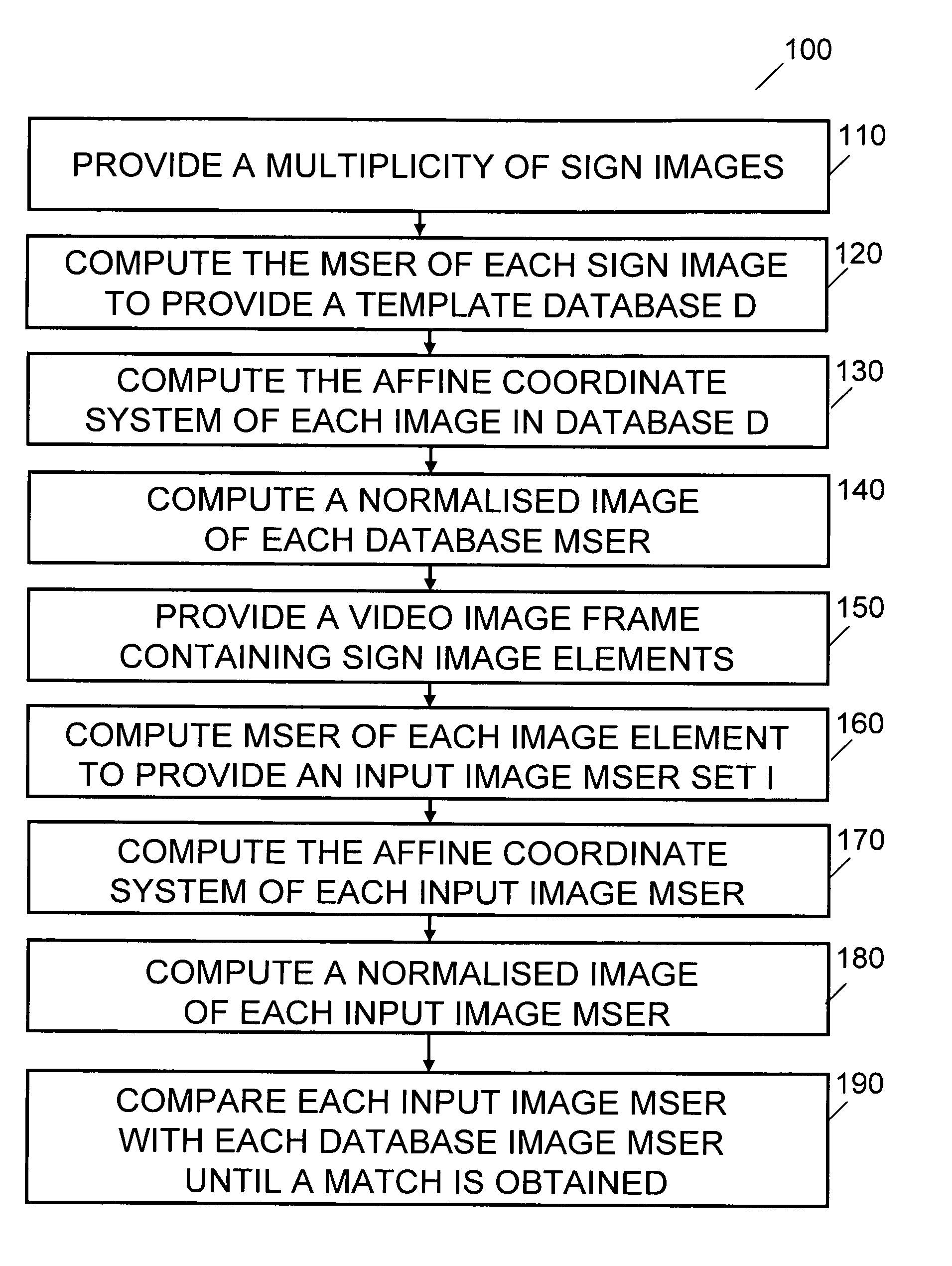
There is provided an efficient, fast image processing apparatus with low error probability for rapidly scrutinizing a digitized video image frame and processing said image frame to detect and characterize features of interest while ignoring other features of said image frame. There is further provided an efficient fast image processing method with low error probability for rapidly scrutinizing a digitized video image frame and processing said image frame to detect and characterize features of interest while ignoring other features of said image frame. In a first embodiment of the invention an image processing apparatus comprises an imaging device coupled to a digital electronic image processor. Video data from the imaging device is linked to a location data source. Objects of interest in a scene are identified by comparing computed Maximally Stable Extremal Regions (MSERs) of captured images with MSERs of images of objects contained in a object template database.

Description

REFERENCE TO RELATED APPLICATION[0001]This application claims the priority of United Kingdom Patent Application No. GB0804466.1 filed on 11 Mar. 2008 by the present inventor.BACKGROUND OF THE INVENTION[0002]The present invention relates generally to the field of automated image identification and in particular to the identification of signs depicted in video image frames.[0003]There is a requirement for efficient methods for rapidly scrutinizing digitized video image frames and classifying and cataloging objects of interest depicted in said video frames. Many examples of methods developed for a range of applications are to be found in the patent literature. Prior art apparatus typically comprises a camera of known location or trajectory configured to survey a scene including one or more calibrated target objects, and at least one object of interest. Most prior art devices are used for capturing video data regarding an object operating in a controlled setting such as an industrial pr...

Claims


Application Information

Patent Timeline
IPC IPC(8): G06K9/00G06K9/68G06V30/144
CPCG06K9/325G06K9/00818G06V20/582G06V20/62G06V30/144G06V10/20G06V10/32G06V10/421
Inventor CROSS, GEOFFREY MARK TIMOTHY
Owner CROSS GEOFFREY MARK TIMOTHY
Learn More