Ultrasonic piezoelectric pump

a piezoelectric pump and ultrasonic technology, applied in the direction of pump components, positive displacement liquid engines, pump parts, etc., can solve the problems of affecting the efficiency of pumping, the cooling of electronic parts is becoming critical, and the conventional piezoelectric pump is not suitable for minimizing electronic products and medical equipment, so as to achieve smooth pumping and easy discharge

Inactive Publication Date: 2009-09-17
KOREA INST OF MACHINERY & MATERIALS
View PDF11 Cites 9 Cited by
  • Summary
  • Abstract
  • Description
  • Claims
  • Application Information

AI Technical Summary

Benefits of technology

[0011]Therefore, the present invention has been made in view of the above problems, and it is an aspect of the present invention to provide an ultrasonic piezoelectric pump in which: a piezoelectric actuator is installed at a center of a fluid pipe; a plurality of fluid-flow holes is formed around the piezoelectric actuator; and a tapered nozzle is tapered forward and downwardly in front of the piezoelectric actuator to force a fluid to be easily discharged and to have difficulty to flow backward so that a fluid can be smoothly pumped by the piezoelectric actuator without a check valve while preventing the fluid from flowing backward.
[0012]It is another aspect of the present invention to provide an ultrasonic piezoelectric pump in which a voltage applied to a piezoelectric device is adjusted to quickly deform the piezoelectric device for the fluid discharge and a frequency is adjusted to have a voltage waveform to force the piezoelectric device to be restored slowly so that a fluid can be smoothly discharged.
[0013]It is still another aspect of the present invention to provide an ultrasonic piezoelectric pump, a piezoelectric device of which is driven by ultrasonic waves to force a fluid to flow while causing flow resonance so that efficiency of heat transfer can be improved.

Problems solved by technology

In general, since parts for small sized electronic products and medical equipment possibly malfunction or are damaged due to heat generated therein because degree of integration of transistors is improved, cooling of the electronic parts is becoming a critical issue in electronic apparatuses using small electronic parts.
As such, since the conventional piezoelectric pump is provided independently from the fluid pipe 300 and the check valves 500 for preventing fluid from flowing backward are provided independently from the pump, the conventional piezoelectric pump is not suitable for minimizing electronic products and medical equipment because it is difficult to make the piezoelectric pump in a small size.

Method used


Image

  • Ultrasonic piezoelectric pump
  • Ultrasonic piezoelectric pump
  • Ultrasonic piezoelectric pump

Examples


first embodiment

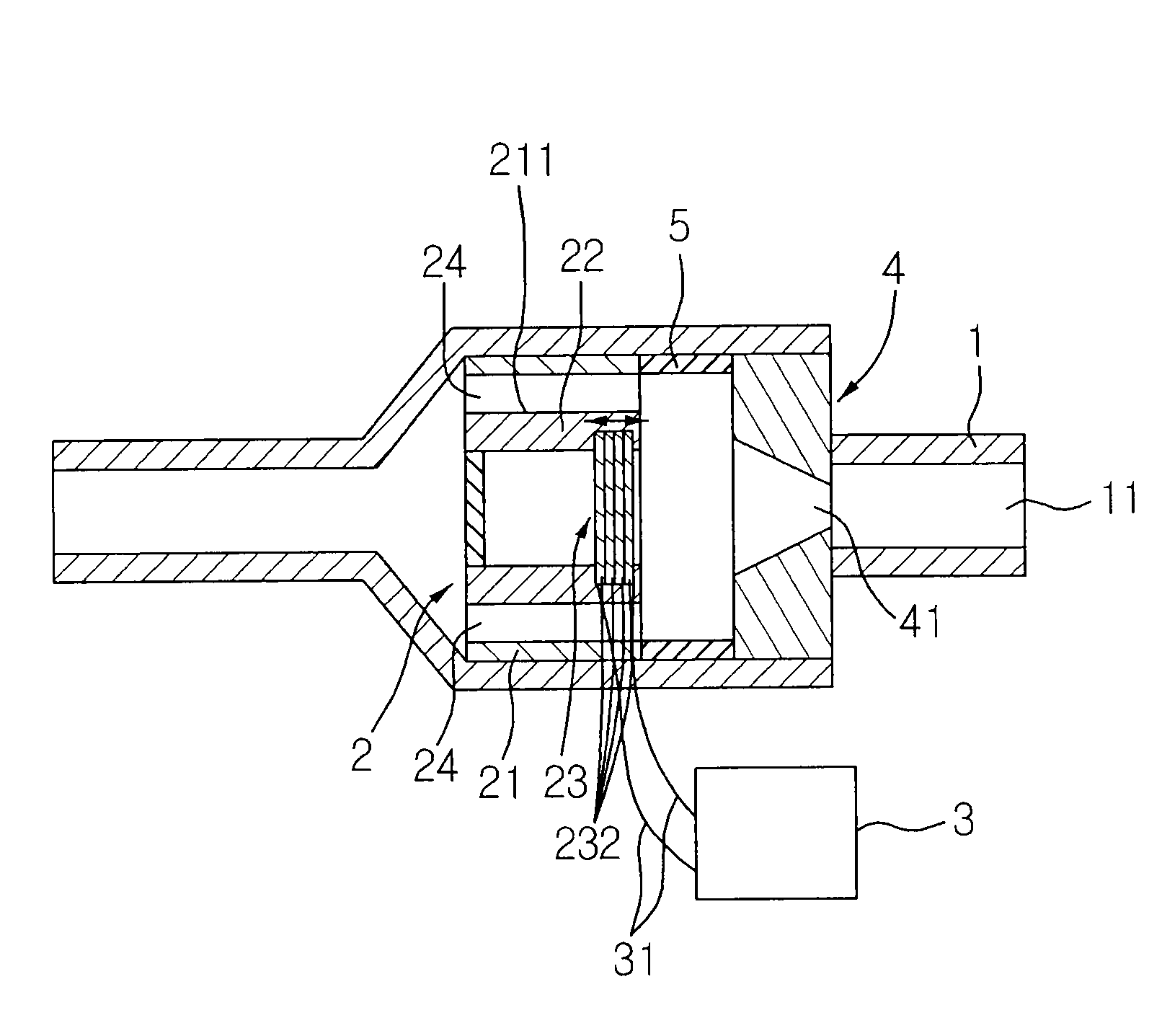
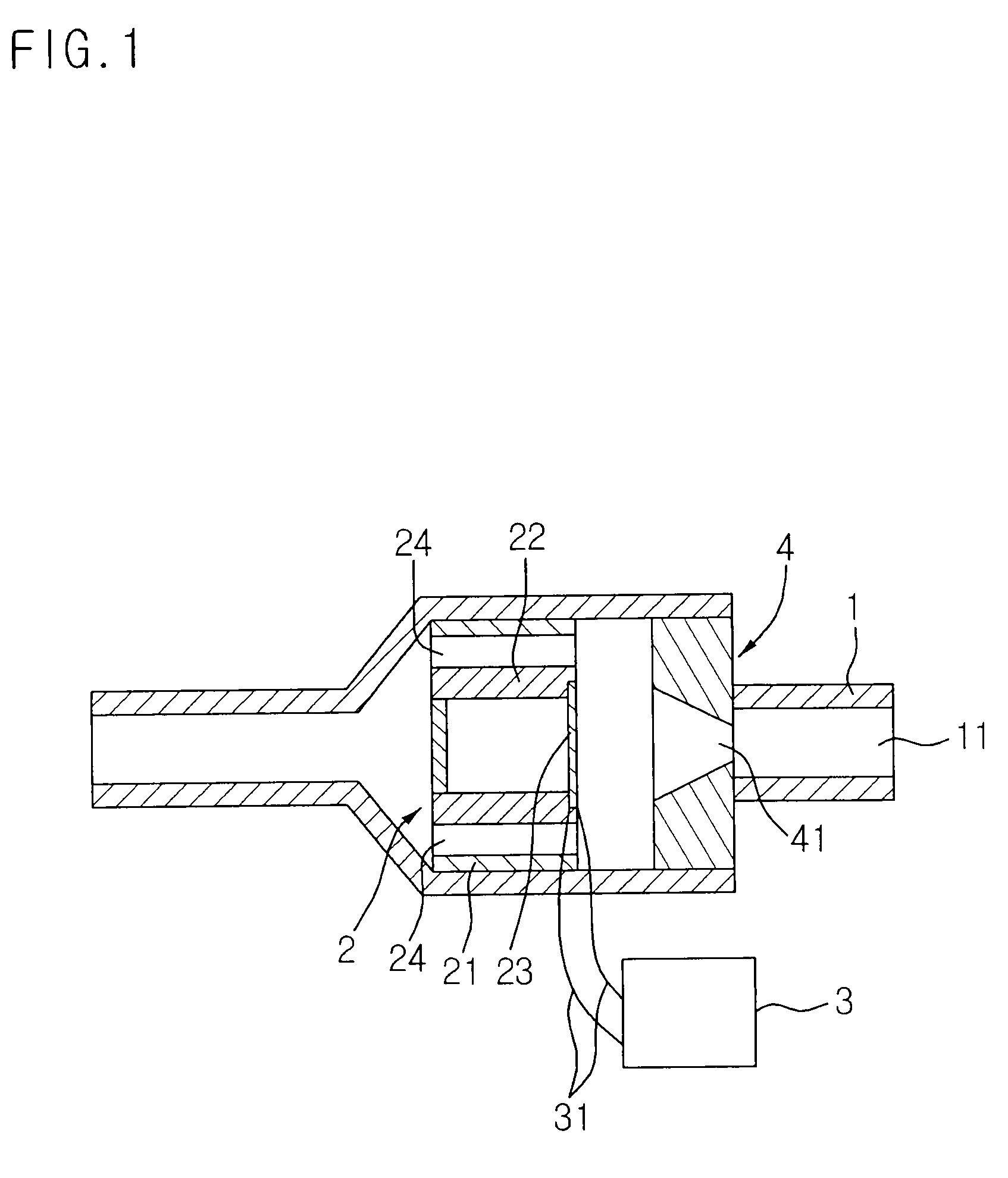
[0034]FIG. 1 is a sectional view illustrating an ultrasonic piezoelectric pump according to the present invention. The ultrasonic piezoelectric pump includes a fluid pipe 1, a piezoelectric pump 2, a controller 3, and a tapered nozzle 4.

[0035]The fluid pipe 1 has a hollow part 11 formed therein through which a fluid flows from a fluid source.

[0036]Moreover, the piezoelectric actuator 2 is inserted into the hollow part 11 and includes a piezoelectric device 23 and a plurality of fluid holes 24.

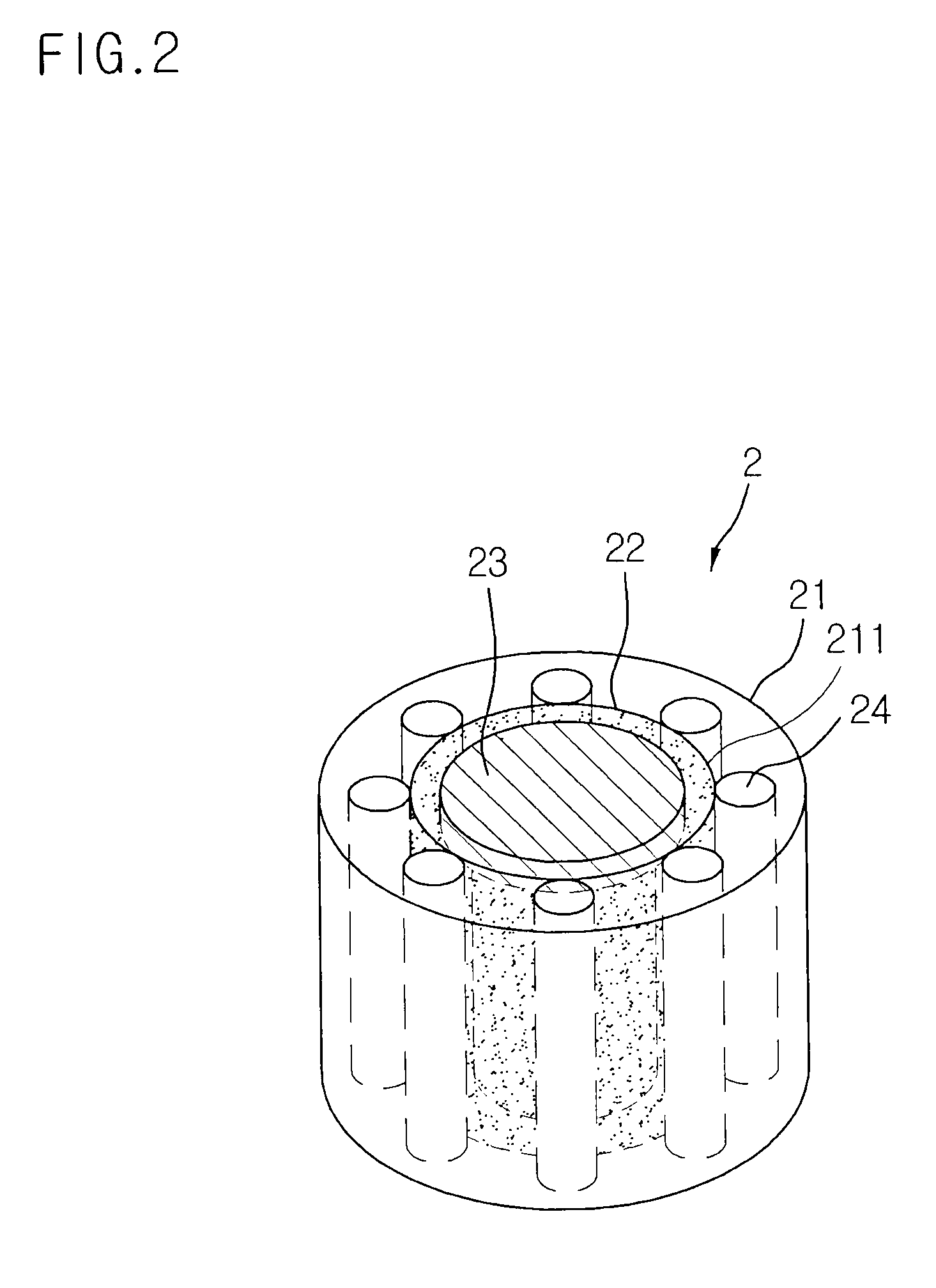
[0037]FIG. 2 is a perspective view illustrating the piezoelectric actuator of FIG. 1. The actuator 2 includes a case 21 with through-holes 211 formed at the center thereof, a frame 22, inserted into the through-holes 211, in which the piezoelectric device 23 is installed to the front side of the frame 22, and the plurality of fluid holes 24 formed in the vicinity of the frame 22 to penetrate the front side to the rear side of the case 21 and to permit the fluid supplied to the fluid pipe 1 to f...

second embodiment

[0041]FIG. 5 is a sectional view illustrating an ultrasonic piezoelectric pump according to the present invention. Hereinafter, structures and operations of the same components as those of FIG. 1 will be omitted.

[0042]Referring to FIG. 5, a distance adjusting circular ring 5 is provided in the hollow part 11 of the fluid pipe 1 between the piezoelectric actuator 2 and the tapered nozzle 4 to adjust a distance from the piezoelectric actuator 2 and the tapered nozzle 4.

[0043]In this case, the distance between the piezoelectric actuator 2 and the tapered nozzle 4 is preferably adjusted by the distance adjusting circular ring 5 to optimize the transmission of kinetic energy of the fluid.

[0044]FIG. 6 is a sectional view illustrating an ultrasonic piezoelectric pump according to a third embodiment of the present invention, and structures and operations of the same components as those of the first and second embodiments of the present invention will be omitted.

[0045]According to this embod...

fourth embodiment

[0060]FIG. 10 is a sectional view illustrating an ultrasonic piezoelectric pump according to the present invention. The ultrasonic piezoelectric pump includes a piezoelectric pump 1, a piezoelectric actuator 2, a controller 3, and a tapered nozzle 4.

[0061]The fluid pump 1 has a hollow part 11 formed therein through which a fluid flows from a fluid source.

[0062]Moreover, the piezoelectric actuator 2 is inserted into and fixed in the hollow part 11, and has a piezoelectric device 23 and a plurality of fluid holes 24.

[0063]Here, the actuator 2 includes a case 21 having a through-hole 211 formed at the center, a frame 22, inserted into the through-hole 211, to which the piezoelectric device 23 is installed, and a plurality of fluid holes 24 formed in the vicinity of the frame 22 to penetrate the front side to the rear side of the case 21 and to permit the fluid supplied to the fluid pipe 1 to flow therethrough.

[0064]The piezoelectric device 23 may include a multi-layer piezoelectric dis...


PUM


Abstract

Disclosed is an ultrasonic piezoelectric pump in which a piezoelectric pump is integrated with a fluid pipe without a check valve so that the structure can be simplified. The pump includes a fluid pipe having a hollow part formed therein to permit a fluid to flow from a fluid source, a piezoelectric actuator inserted into the hollow part and including a piezoelectric device and a plurality of fluid holes, a controller connected to a lead wire to apply a driving power to the piezoelectric device, and a tapered nozzle inserted into the hollow part in front of the piezoelectric actuator and tapered forward and downwardly.

Description

BACKGROUND OF THE INVENTION[0001]1. Field of the Invention[0002]The present invention relates to a piezoelectric pump, and more particularly, to an ultrasonic piezoelectric pump in which a piezoelectric pump is integrated with a fluid pipe without a check valve so that the structure can be simplified.[0003]2. Description of the Related Art[0004]In general, since parts for small sized electronic products and medical equipment possibly malfunction or are damaged due to heat generated therein because degree of integration of transistors is improved, cooling of the electronic parts is becoming a critical issue in electronic apparatuses using small electronic parts.[0005]It is proposed a refrigerant circulation system using a piezoelectric pump, as a solution for cooling the small sized electronic components, for suctioning liquid refrigerant and for vibrating the liquid refrigerant by applying a force to the liquid refrigerant to discharge the refrigerant in a desired phase(?).[0006]FIG...

Claims


Application Information

Patent Timeline
Patent Type & Authority Applications(United States)
IPC IPC(8): F04B17/00F04B35/04
CPCF04B53/08F04B17/003
Inventor HAM, YOUNG-BOGPARK, JUNG-HOJO, JEONG-DAIYUN, SO-NAMCHOI, BYUNG-OH
Owner KOREA INST OF MACHINERY & MATERIALS
Why Eureka
Try Eureka