Seal apparatus of gear pump

a gear pump and seal device technology, applied in the direction of machines/engines, rotary/oscillating piston pump components, liquid fuel engines, etc., can solve the problems of damage to the seal member, and achieve the effect of suppressing the increase of friction, preventing the jamming (bitten state) of the seal member, and increasing the friction between the side plate and the gear

Inactive Publication Date: 2009-09-17
HITACHI LTD
View PDF9 Cites 21 Cited by
  • Summary
  • Abstract
  • Description
  • Claims
  • Application Information

AI Technical Summary

Benefits of technology

[0004]On the other hand, in the case where the clearance between the backup ring and the inner surface of the housing and the clearance between the backup ring and the side plate are shortened by enlarging a diameter the backup ring in order to prevent this jamming (bitten state); the side plate is pressed by an elastic force of the backup ring, and thereby a friction between the side plate and a gear is increased.
[0005]It is therefore an object of the present invention to provide a seal apparatus of a gear pump, devised to prevent the jamming (bitten state) of the seal member and also to suppress the increase of friction.

Problems solved by technology

However, in the above technique, in the case where a space between the side plate and the inner surface of the housing is large, there has been a possibility that the seal member is jammed (pushed) into a clearance between the backup ring and the inner surface of the housing or into a clearance between the backup ring and the side plate, and thereby the seal member is damaged.

Method used


Image

  • Seal apparatus of gear pump
  • Seal apparatus of gear pump
  • Seal apparatus of gear pump

Examples


first embodiment

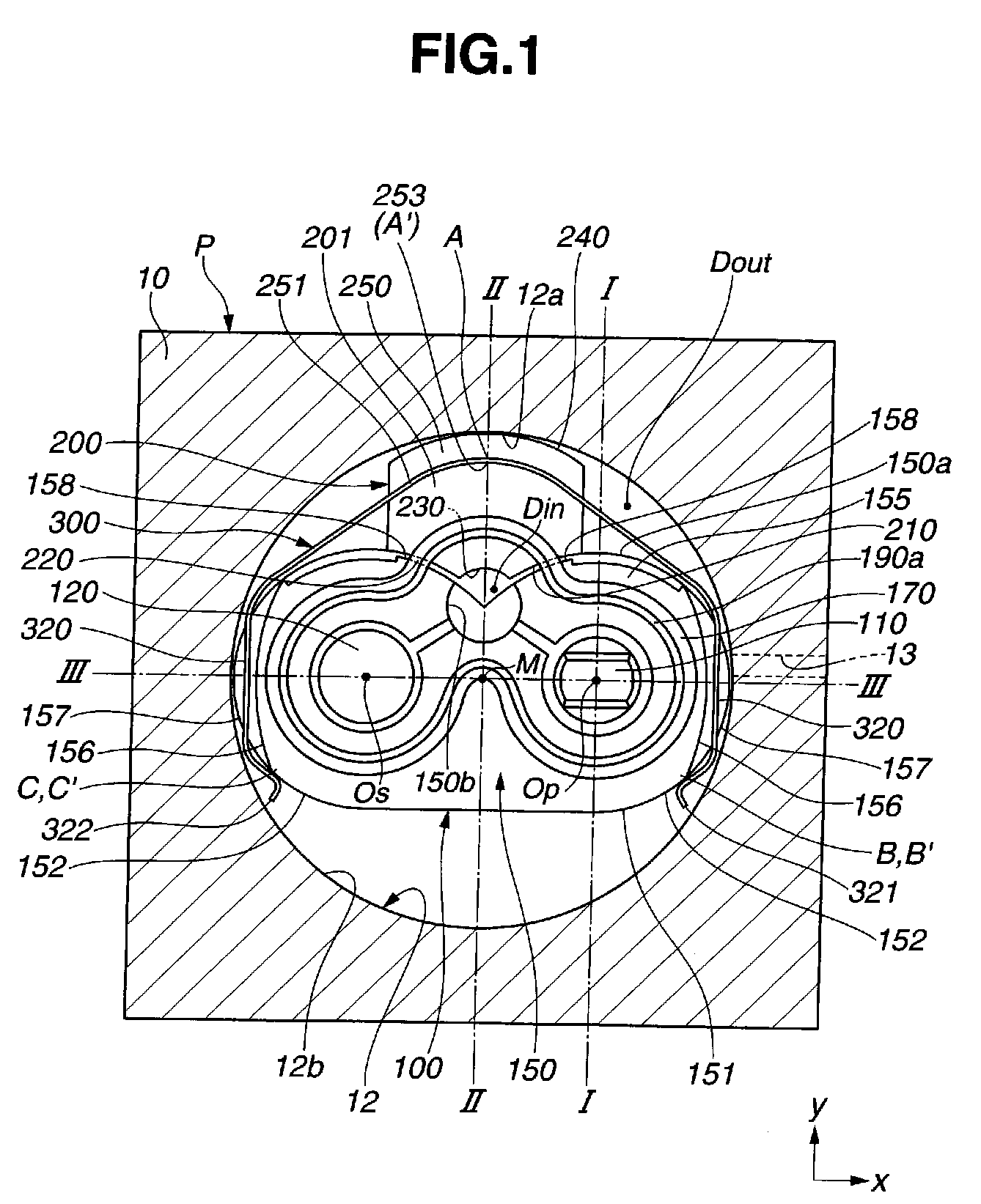
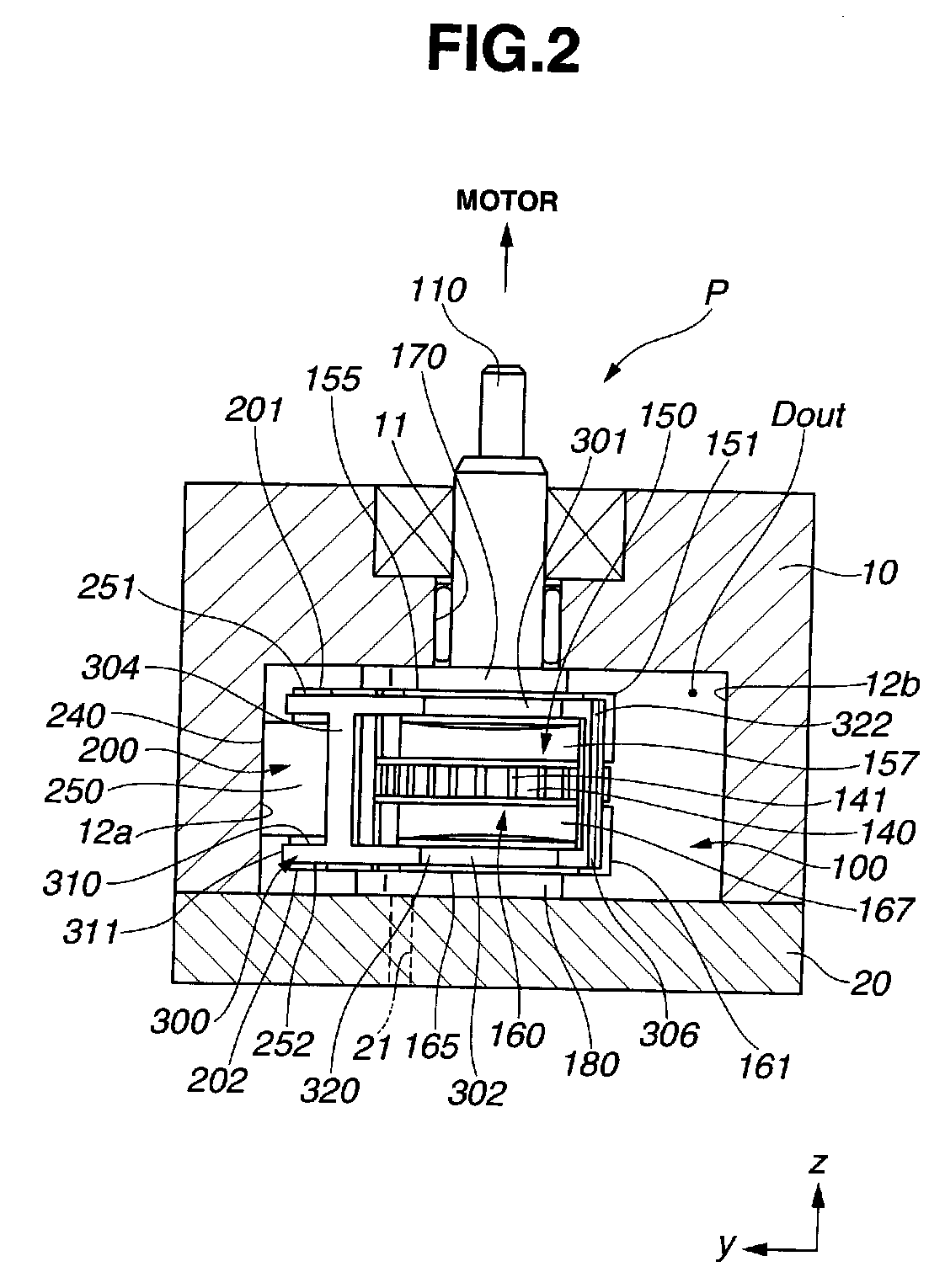
[0056]FIG. 1 is a front view of a gear pump P as viewed from z-axis positive side. FIG. 2 is a side view of the gear pump P as viewed in x-axis positive direction. FIG. 3 is a cross-sectional view of FIG. 1, taken along a line I-I. In FIGS. 1 and 2, only parts corresponding to a housing 10 and a housing cover 20 are shown in cross section.

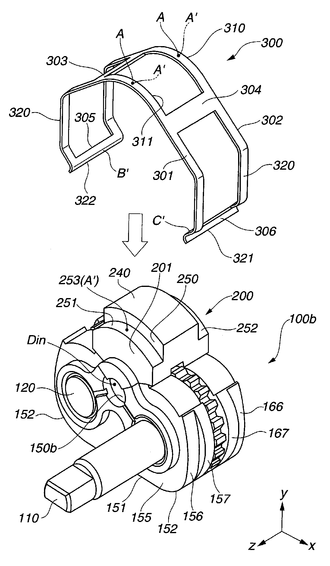
[0057]In the respective drawings, a direction from a driven shaft 120 toward a drive shaft 110 in a pump assembly 100 is defined as x-axis positive direction. Moreover, a direction perpendicular to x-axis and toward a seal block 200 of the pump assembly 100 is defined as y-axis positive direction. Moreover, a direction that is coaxially with the drive shaft 110 and is from the pump assembly 100 toward a motor (not shown) is defined as z-axis positive direction. FIG. 4 is an oblique perspective view of the pump assembly 100. FIG. 5 is a front view of the pump assembly 100 as viewed from y-axis positive side. FIG. 6 is a front view of the pump assemb...

embodiment

According to Present Invention

[0141]In the first embodiment according to the present invention; there are provided the backup ring 190a, the clearance h5 between the backup ring 190a and the shoulder portion 159 under the state of pre-assembling, and the clearance h6 between the shoulder portion 159 and the z-axis negative side portion 176 of the seal ring 170 under the state of pre-assembling.

[0142]Therefore, the seal ring 170 does not immediately become in contact with the shoulder portion 159 even if the seal ring 170 is pressed from the discharge region Dout. At this time, the clearance h6 located on a y-axis positive side of the z-axis negative side portion 176 of the seal ring 170 functions as the space to which a part of material of the seal ring 170 moves (escapes).

[0143]The z-axis negative side portion 176 of the seal ring 170 includes a contact portion 176a which abuts on the backup ring 190a, and a noncontact portion 176b which does not abut on the backup ring 190a. The h...

first modified example of first embodiment

[0171]FIG. 32 is a view showing an example in which the cross section of seal ring 170 is modified by forming a shape including a chamfer portion 177 provided by chamfering one diagonal corner of the rectangular seal ring 170. The backup ring 190a is formed substantially in a triangular shape in cross section, and is placed on the chamfer portion 177 of the seal ring 170′.


PUM


Abstract

A seal apparatus includes at least one pair of gears; a side plate arranged adjacent to the pair of gears; and a housing sandwiching the side plate. At least one of the side plate and the housing includes a shoulder portion. The seal apparatus further includes a seal member arranged between the housing and the side plate and arranged at the shoulder portion. The seal member separates a low pressure area from a high pressure area in a radial direction of the gear. The shoulder portion is located in the low pressure area. At least a part of the seal member faces the high pressure area. The seal apparatus further includes a backup member reinforcing the seal member and facing a tip portion of the shoulder portion; and a containing portion formed between a root portion of the shoulder portion and the seal member to be capable of containing a part of the seal member at least when the seal member is elastically deformed.

Description

BACKGROUND OF THE INVENTION[0001]The present invention relates to a seal apparatus of a gear pump which is favorably used as, for example, a hydraulic source of a brake system for vehicle.[0002]Japanese Utility Model Application Publication No. H03(1991)-123993 discloses a previously-proposed gear pump. The gear pump in this technique includes a drive shaft, a driven shaft, a pair of side plates and a seal member in a housing. Because the seal member is an elastic body, a backup ring having a higher hardness than the seal member is provided on a low-pressure side of the side plate (on an inner circumferential side of the side plate). Thereby, it is suppressed that the seal member is excessively deformed. The seal member and the backup ring are held to be sandwiched between the side plate and an inner surface of the housing.SUMMARY OF THE INVENTION[0003]However, in the above technique, in the case where a space between the side plate and the inner surface of the housing is large, the...

Claims


Application Information

Patent Timeline
Patent Type & Authority Applications(United States)
IPC IPC(8): F04C15/00F04C2/14F16J15/10F16J15/02
CPCF04C2/18F16J15/3208F16J15/164F04C15/0003
Inventor MARUO, RYOHEIKOIZUMI, TOSHIHIROSAITA, NORIHIRO
Owner HITACHI LTD
Why Eureka
Try Eureka