Shape-forming shutter apparatus and shutter piece thereof

a technology of shape-forming shutters and shutter pieces, which is applied in the field of shape-forming shutters, can solve the problems of troublesome handling of the apparatus and inability to shape food dough into a stable form

Inactive Publication Date: 2009-09-17
RHEON AUTOMATIC MASCH CO LTD
View PDF13 Cites 10 Cited by
  • Summary
  • Abstract
  • Description
  • Claims
  • Application Information

AI Technical Summary

Benefits of technology

[0018]The present invention causes the shaping surface of each shutter piece and the sliding surface of the neighboring shutter piece to be always kept slidably in pressure contact with each other in the shutter apparatus. As a result, the present invention makes it possible to prevent a fine gap from occurring between the shaping surface and the sliding surface, and accordingly to solve the above-described existing problems.

Problems solved by technology

However, these apparatuses have a problem that they are incapable of shaping food dough into a stable form when the abrasion or the like between neighboring shutter pieces forms a gap between the neighboring shutter pieces to allow a part of the food dough to go into the gap.
However, this apparatus has a problem that the handling of the apparatus is troublesome, because the fitting position of the eccentric pin to which the connecting member is locked needs to be adjusted, in a case where an abrasion between the two neighboring shutter pieces or the like forms a gap inadequately.

Method used


Image

  • Shape-forming shutter apparatus and shutter piece thereof
  • Shape-forming shutter apparatus and shutter piece thereof
  • Shape-forming shutter apparatus and shutter piece thereof

Examples


first embodiment

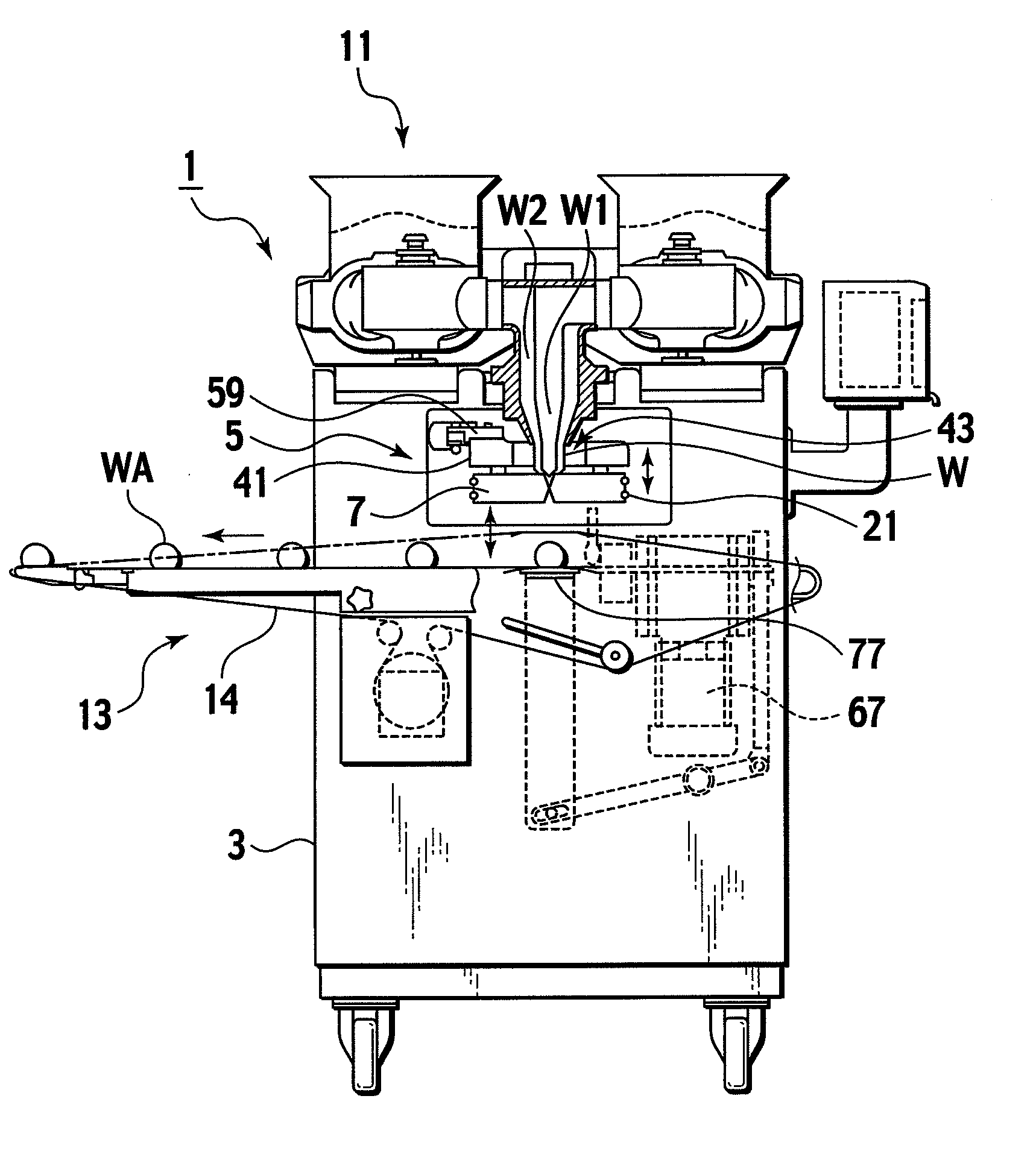
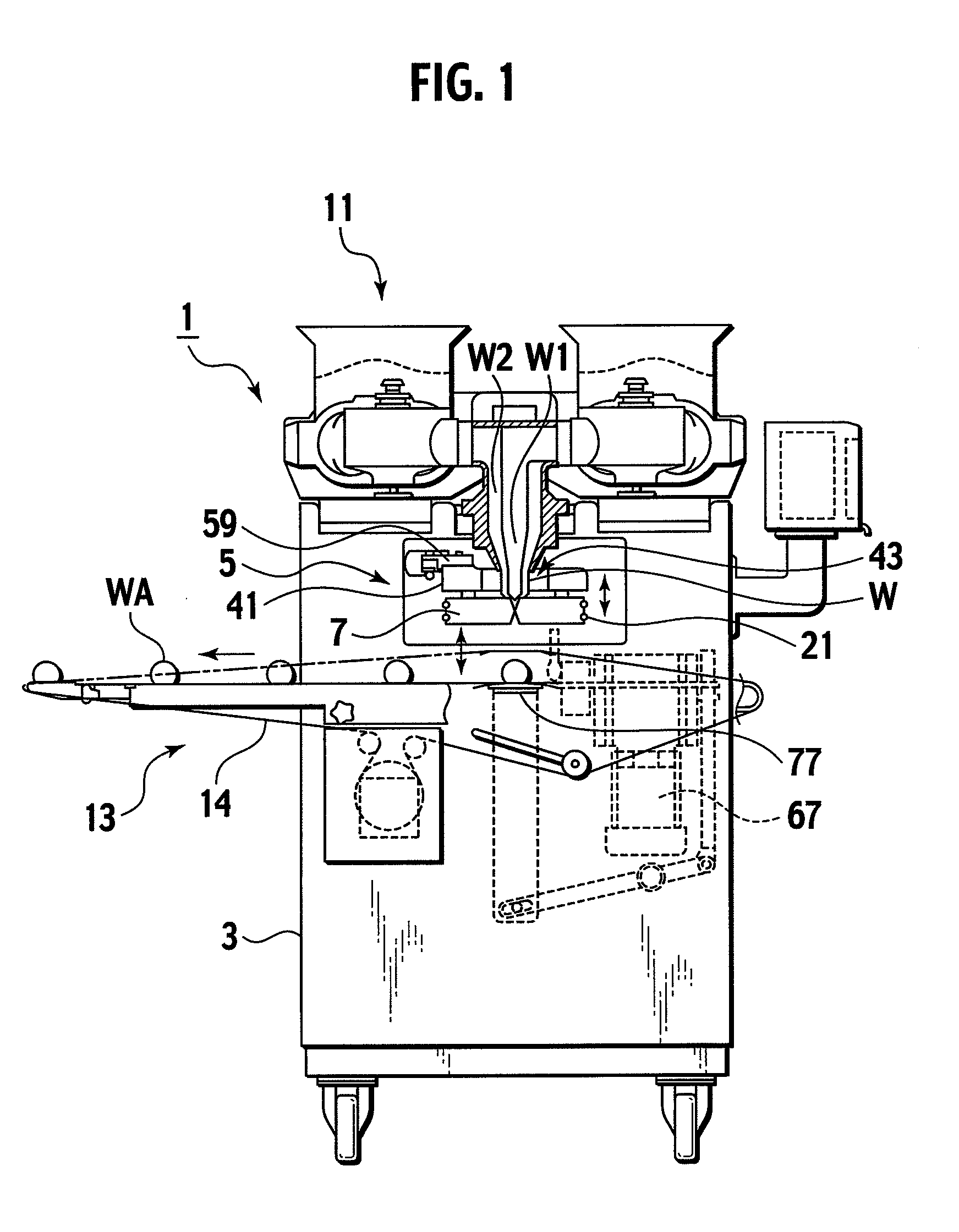
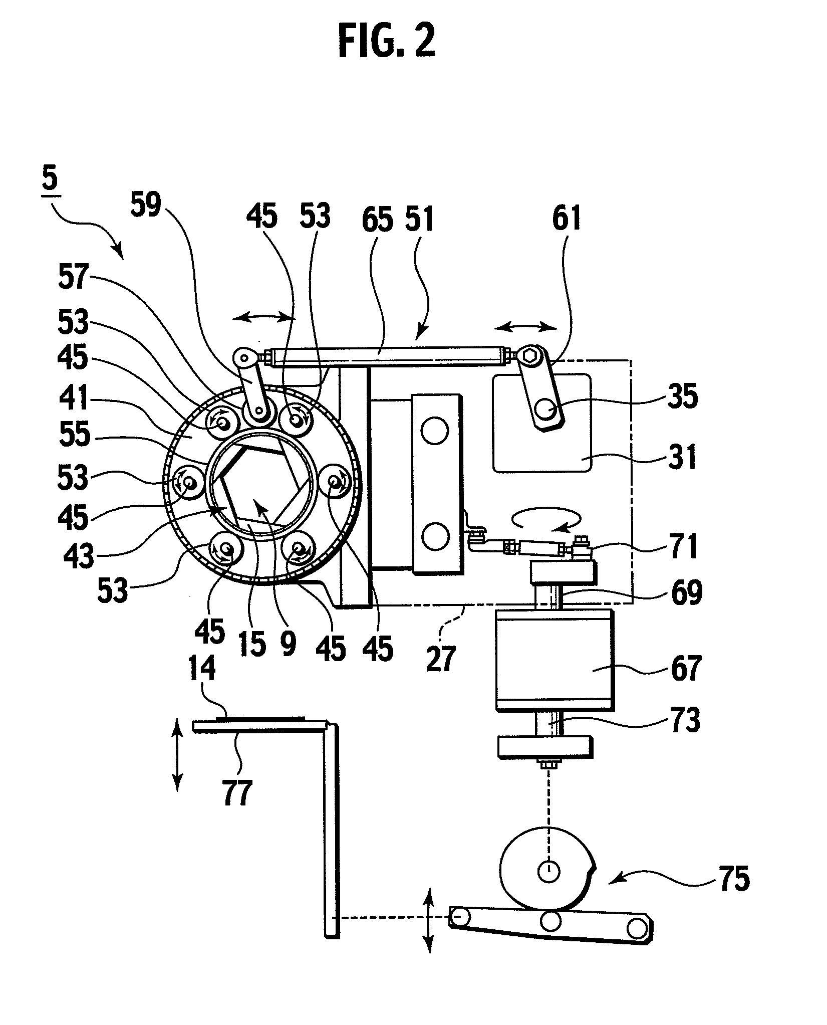
[0033]Descriptions will be provided for a food producing machine 1 including a shutter apparatus according to the present invention by use of the drawings. FIG. 1 is an explanatory plan view showing a schematic of the food producing machine 1. FIG. 2 is an explanatory plan view showing a schematic of a cutting / shaping apparatus 5. FIGS. 3 to 6 are explanatory auxiliary plan views each showing how a shutter assembly 7 operates. FIG. 7 is an explanatory perspective view showing schematics respectively of a shutter piece 15 and a swingable member 47.

[0034]The food producing machine 1 cuts and shapes multiple times a two-layered bar-shaped food dough W including a filling W1 and a crust W2, and concurrently conveys food products WA in a conveyance direction (in a leftward direction in FIG. 1). Its base is a box-shaped main body frame 3. An example of the shutter apparatus, the cutting / shaping apparatus 5 is provided in the center portion of the main body frame 3. This cutting / shaping ap...

second embodiment

[0056]The shaping surface 17 of the shutter piece 15 includes an upper vertical part 17d, a slant part 17e and a lower vertical part 17f, starting from the top surface. The sliding surface 19 is formed so as to slidably engage with the shaping surface 17.

[0057]In addition, an example of the contact pressure biasing means is an elastic member 81, such as the O-ring, which is put on all the shutter pieces 15 and the sliding members 47. The elastic member 81 is put thereon by being stretchingly wound around locking grooves 83a of locking parts 83 and locking grooves 47e of locking parts 47d provided to lower portions of the swingable members 47, the locking parts 83 each fixedly provided to a rear end portion of the shutter piece 15 which is located at the other side of a front end portion of the shutter piece 15 where the shaping surface 17 and the sliding surface 19 intersect each other. Specifically, each shutter piece 15 is biased in a direction in which the locking part 83 comes ...

third embodiment

[0063]FIGS. 10(a) and (b) as well as FIGS. 11(a) and (b) show a shutter apparatus according to the present invention. This shutter apparatus is a modification of a shutter apparatus described in Japanese Examined Patent Application Publication No. Hei. 4-52738.

[0064]The overall configuration of the shutter apparatus according to the third embodiment is publicly known as described in the Japanese Examined Patent Application Publication No. Hei. 4-52738. For this reason, descriptions will be provided for the schematic thereof. The shutter apparatus is configured to include a regular polygonal guide hole 103 in a frame 101. Shutter pieces 107 are provided inside this guiding hole 103 so as to respectively correspond to inner wall parts 105 constituting the polygon into which the guiding hole 103 is formed. The shutter pieces 107 are capable of sliding along the corresponding inner wall parts 105. Each shutter piece 107 is shaped like a trapezoid and its external shape is similar to tha...


PUM

PropertyMeasurementUnit
pressureaaaaaaaaaa
elasticaaaaaaaaaa
shapeaaaaaaaaaa

Abstract

Disclosed is an shape-forming shutter apparatus including a plurality of shutter pieces, each having an shaping surface and a sliding surface, which are arranged in a circle with the shaping surface of each shutter piece being slidably in sliding contact with the sliding surface of the neighboring separate shutter piece, and the shape-forming shutter apparatus being capable of dilating and contracting an opening part surrounded by the shaping surfaces respectively of the plurality of shutter pieces. The shape-forming shutter apparatus includes pressure contact biasing means for always keeping the shaping surface of each shutter piece and the sliding surface of the neighboring shutter piece slidably in pressure contact with each other. The pressure contact biasing means is a ring-shaped elastic member for biasing the shutter pieces equally in such a direction to close the opening part. The elastic member is stretchingly wound around the shutter pieces in an end of each shutter piece, which end is separate away from the other end thereof where the shaping surface of the shutter piece and the sliding surface of the neighboring shutter piece intersect each other.

Description

TECHNICAL FIELD[0001]The present invention relates to a shape-forming shutter apparatus for shaping food products such as round rice cakes, buns each with a bean-jam filling and sweet buns, as well as to a shutter piece thereof. Specifically, the present invention relates to a food shape-forming shutter apparatus and a shutter piece thereof, which are used for a cutting apparatus for dividing a continuously-fed bar-shaped food dough into the above food products, as well as for a sealing apparatus for wrapping a filling with a sheet crust (a piece of food dough).BACKGROUND ART[0002]There have been various types of apparatus for cutting and shaping food products as apparatuses for cutting a bar-shaped food dough, for example. The apparatus for cutting and shaping food products repeatedly opens and closes a cutting opening part in a center portion surrounded by shutters multiple times while feeding a bar-shaped food dough in a dual structure including a filling and a crust to the cutti...

Claims


Application Information

Patent Timeline
Patent Type & Authority Applications(United States)
IPC IPC(8): B28B7/14A23G3/02B26D1/45B26D3/18
CPCA21C11/103A23P1/08B26D2007/0037B26D1/30B26D3/16A23P1/086A23P20/00A23P20/20
Inventor ONOGUCHI, KAZUYOSHI
Owner RHEON AUTOMATIC MASCH CO LTD
Why Eureka
Try Eureka