Inductive power transfer control using energy injection

a technology of inductive power transfer and energy injection, which is applied in the direction of electric variable regulation, process and machine control, instruments, etc., can solve the problems of unpredicted voltage and current overshoot during load transients, complicated controller design for these power supplies, and high cos

Active Publication Date: 2015-08-27
AUCKLAND UNISERVICES LTD
View PDF6 Cites 3 Cited by
  • Summary
  • Abstract
  • Description
  • Claims
  • Application Information

AI Technical Summary

Benefits of technology

[0004]It is an object of the present invention to provide an improved IPT system control method or apparatus, or to provide an approved IPT system power supply

Problems solved by technology

This makes the controller design for these power supplies complicated and costly.
In practice, controlling the power available to a pick up 4 can be problematic, and in existing systems attempts to pr

Method used


Image

  • Inductive power transfer control using energy injection
  • Inductive power transfer control using energy injection
  • Inductive power transfer control using energy injection

Examples


Embodiment Construction

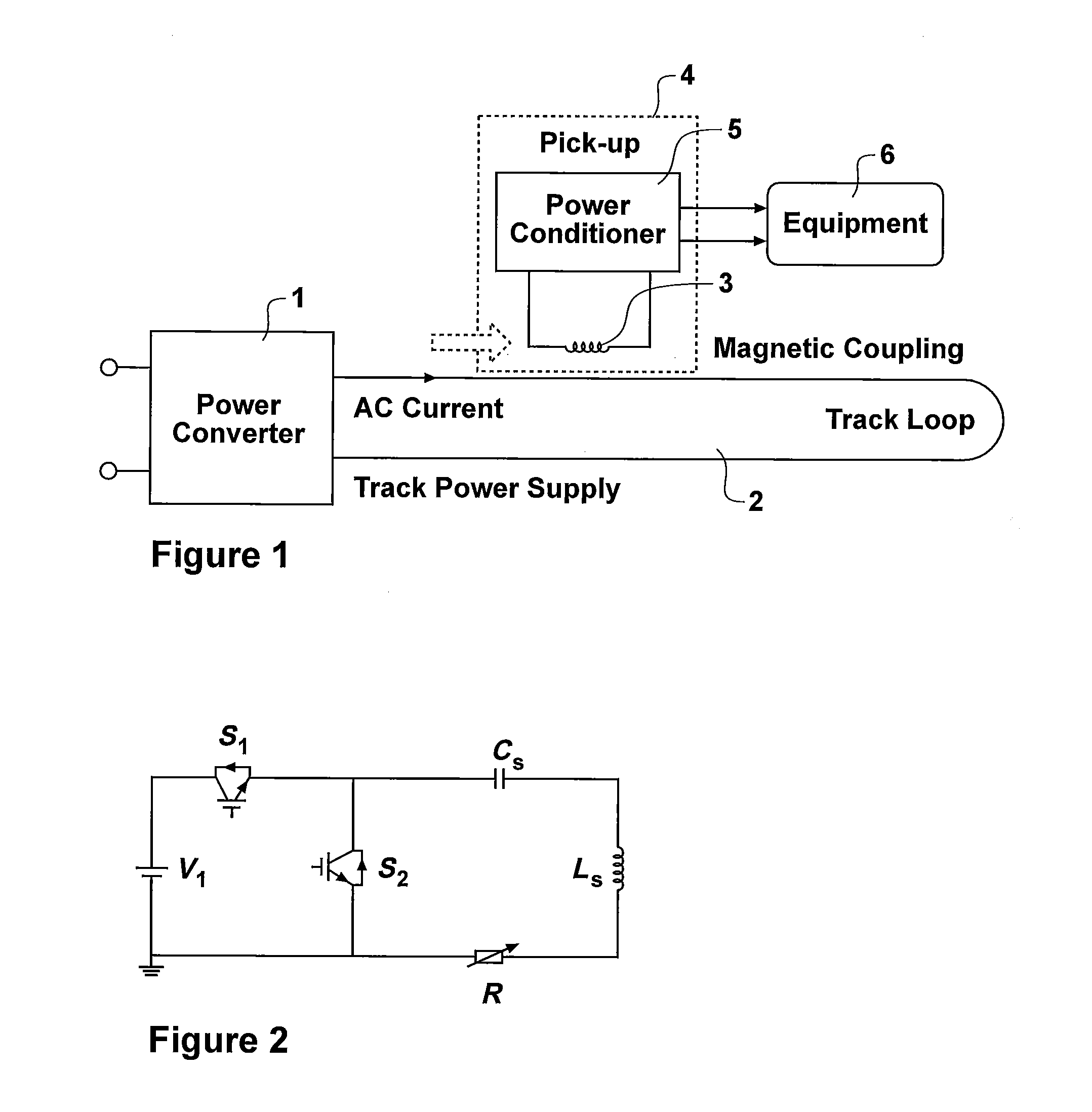
[0061]The invention proposes a new form of control for IPT systems, or IPT primary power supplies, in which discrete energy injection is used to control the primary power controller and thus control the IPT system as required. In particular, energy injection according to the present invention allows the power available to one or more pick ups to be controlled, as will be described further below.

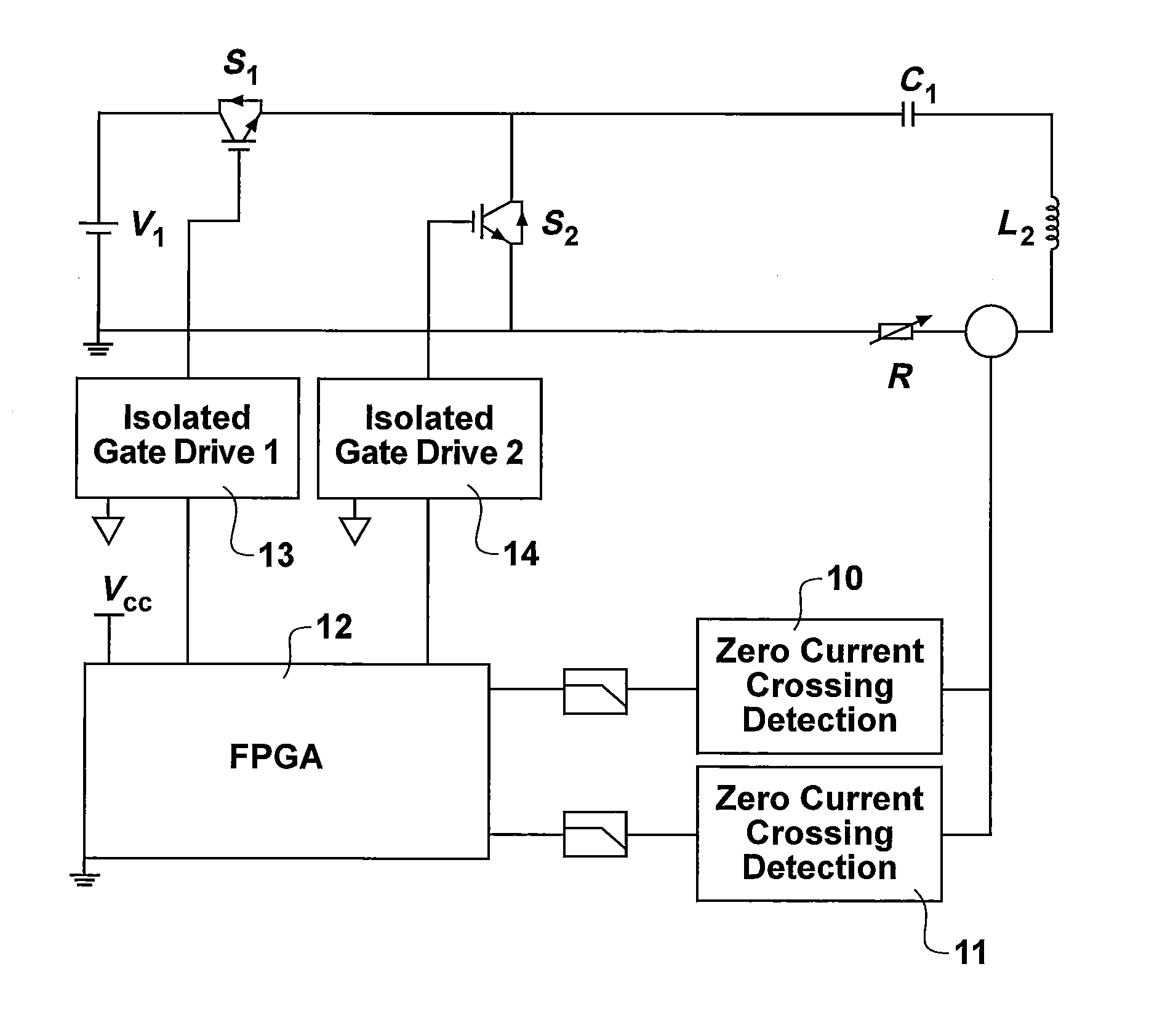
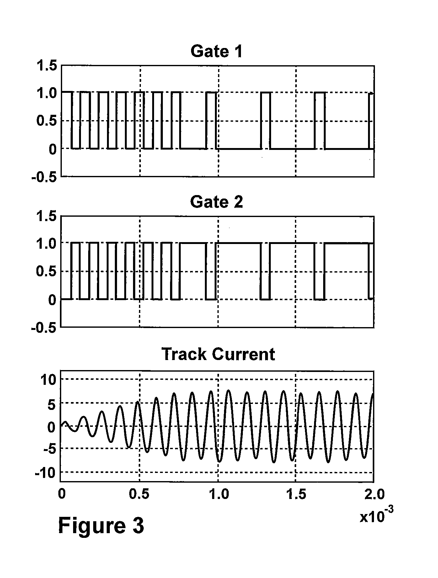
[0062]Referring to FIG. 2, one example of a power converter for use according to the present invention is shown. Switches S1 and S2 are connected as shown with a resonant circuit comprising inductance LS and capacitance C. In practice, inductance LS comprises the track 2 as described with reference to FIG. 1, and capacitance CS is selected to tune the track at a desired resonant frequency. Load resistor R represents a variable load. As will be appreciated by a person skilled in the art the switches S1 and S2 may be operated to allow the resonant circuit to resonant.

[0063]For example, when swi...


PUM


Abstract

The invention relates to inductive power transfer (IPT) systems, and has particular relevance to control of IPT systems, and to operation of IPT system primary power supplier. There is provided a method for controlling an IPT system primary power supply having a switched resonant circuit; the method comprising: determining the value of a parameter of the system; determining an energy injection switching pattern having a duration dependent on the parameter value; controlling the resonant circuit according to the determined energy injection switching pattern.

Description

FIELD OF THE INVENTION[0001]This invention relates to inductive power transfer (IPT) systems, and has particular relevance to control of IPT systems, and to operation of IPT system primary power supplies.BACKGROUND[0002]Inductive power transfer (IPT) systems are well known. An example of a typical IPT system is shown in FIG. 1 in which a power supply 1 which is typically provided in the form of a converter, energises a primary conductive path or track 2. The power supply typically generates a high frequency current along the track 2, which is usually a discrete coil, but may in other embodiments comprise a single loop. The magnetic field generated in the track 2 enables a pick up coil 3 of a pick up device 4 to be coupled inductively to the track. The pick up 4 includes control circuitry 5 which conditions power received so as to provide an appropriate power supply to load 6.[0003]To generate the high frequency current in track 2, the operating frequency of switches in the power sup...

Claims


Application Information

Patent Timeline
IPC IPC(8): H02J5/00H02J17/00H02J7/02H02M3/158H01F38/14
CPCH02J5/005H02M3/158H02J17/00H02J7/025H01F38/14H02M3/3376H02J50/10H02J7/00712Y02B70/10H02M1/0058H02J50/80H02J50/90H02J50/12
Inventor BUDGETT, DAVID MORTIMERHU, AIGUOMCCORMICK, JOHN DANIEL
Owner AUCKLAND UNISERVICES LTD
Why Eureka
Try Eureka