Electrical Connector with Fault Closure Lockout

a technology of fault closure and electrical connector, which is applied in the direction of couplings/cases, coupling device connections, electrical apparatus, etc., can solve the problems of electrical connector not being electrical connectors cannot be replaced, and electrical connectors are not suitable for further use, so as to prevent the resetting of a moveable member

Active Publication Date: 2009-09-17
EATON INTELLIGENT POWER LTD
View PDF101 Cites 13 Cited by
  • Summary
  • Abstract
  • Description
  • Claims
  • Application Information

AI Technical Summary

Benefits of technology

[0006]The invention relates to preventing the resetting of a moveable member of an electrical connector after a fault closure. When an electrical connector and a cable connector are engaged together during a fault closure, a piston-contact element with a female contact moves forward within the electrical connector to engage a male contact in the cable connector. The piston-contact element moves forward until a piston contact stop on the piston-contact element engages a stop ring in the electrical connector, which prevents further forward movement of the piston contact element. Additionally, a piston lockout member on the piston-contact element prevents movement of the piston-contact element in the opposite direction, thereby preventing the-resetting of the piston-contact element to its original position. More specifically, the piston lockout member of the piston-contact element engages the stop ring in the electrical connector to prevent movement of the piston-contact element to its original position.

Problems solved by technology

However, during fault closure or short circuit conditions, a substantial arc can occur between the contact elements of the connectors, resulting in catastrophic failure of the electrical connector including extensive damage and possible explosion.
After such a fault closure, the electrical connector is not suitable for further use and must be replaced.
More specifically, the substantial arc generated during fault closure damages the female contact of the electrical connector such that the female contact will not perform during a subsequent fault closure.
However, linemen in the field sometimes reset the piston in the electrical connector by forcing the piston back into its original position before the fault closure.
During a subsequent fault closure, the female contact of the electrical connector will not completely engage the male contact of the cable connector, and the fault closure will not be completed.

Method used


Image

  • Electrical Connector with Fault Closure Lockout
  • Electrical Connector with Fault Closure Lockout
  • Electrical Connector with Fault Closure Lockout

Examples


Embodiment Construction

[0023]The following description of exemplary embodiments refers to the attached drawings, in which like numerals indicate like elements throughout the figures.

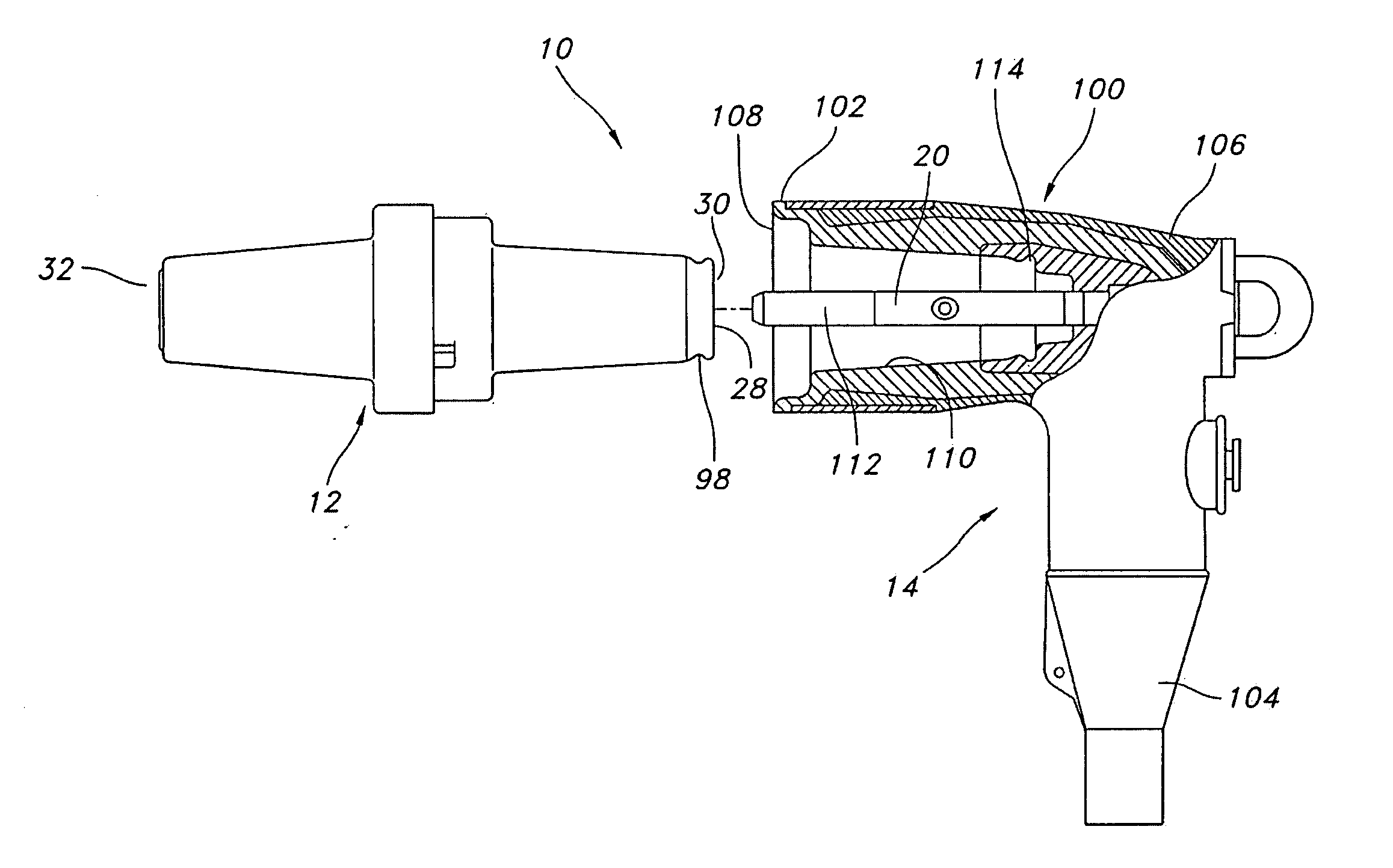
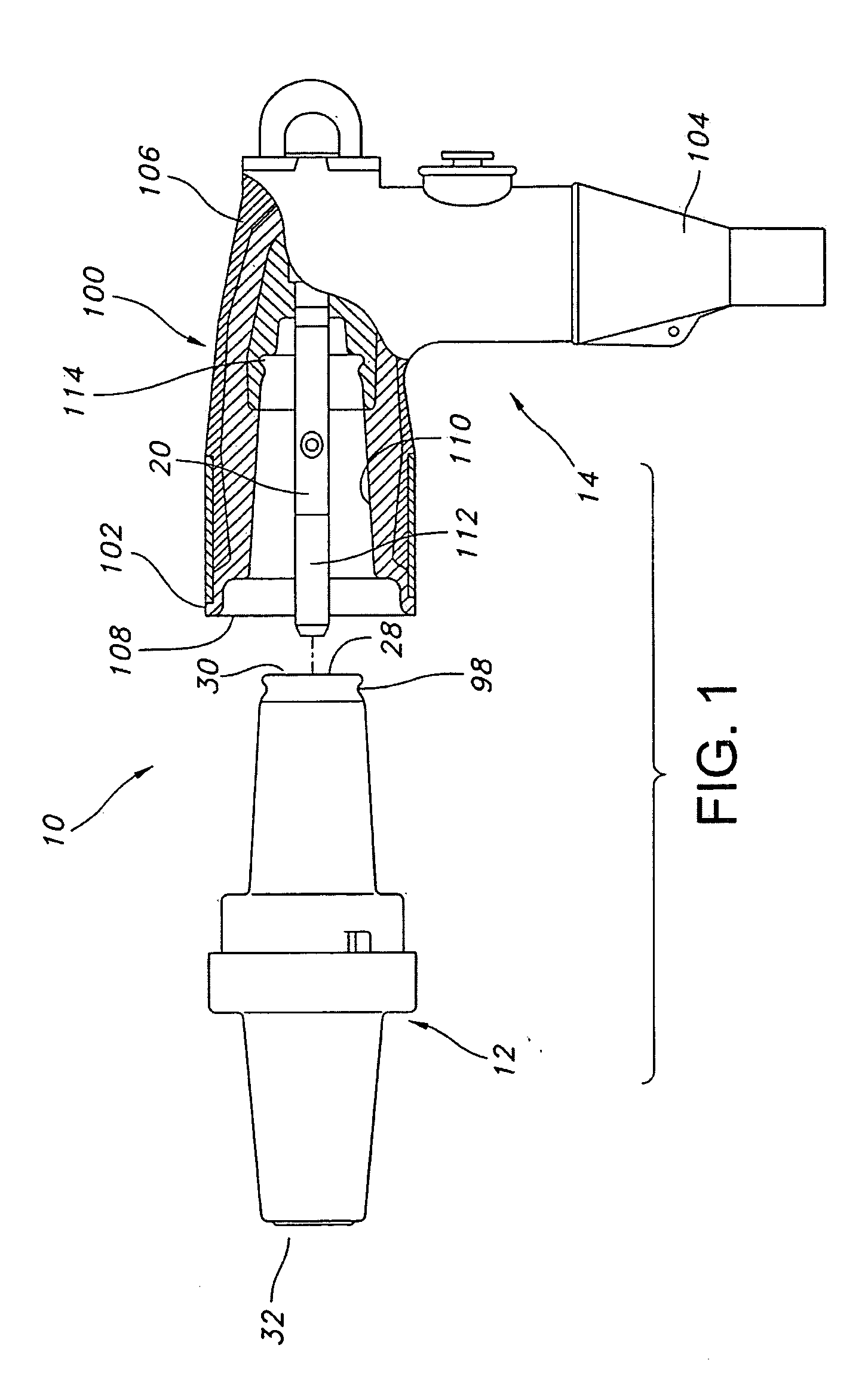
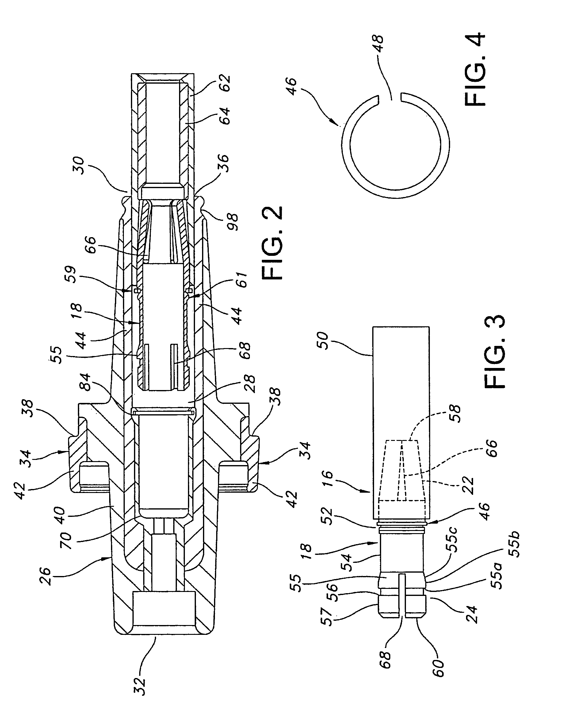
[0024]Referring to FIGS. 1-15, an electrical connector assembly 10 of a power distribution system includes an electrical connector 12, such as a high-voltage bushing insert, adapted to mate with an electrical device 14, such as an elbow cable-connector. As best seen in FIGS. 2-3, the electrical connector 12 includes a housing 26 with an inner bore 28 for receiving a snuffer tube assembly 16. The snuffer tube assembly has a piston-contact element 18 that engages a contact element 20 of the cable connector 14. The piston-contact element 18 is movable between first and second axially spaced positions within an inner bore 28 of the electrical connector 12. During fault closure, first and second contact portions 22, 24 of the piston-contact element 18 move toward the contact element 20 of the cable connector 14 to accelerate engage...


PUM


Abstract

An electrical connector, such as a bushing insert, with a fault-closure lockout feature includes a housing with an inner bore having opposite ends. One end has an opening providing access to the inner bore. A piston-contact element is movable between first and second axially spaced positions within the inner bore. During fault conditions, the piston-contact element moves from the first position to the second position to accelerate connection with a male contact of another electrical connector, such as a cable connector, thereby inhibiting the formation of flashover or electrical arc. After fault closure, a lockout member on the piston-contact element prevents moving the piston-contact element from the second position to the first position.

Description

FIELD OF THE INVENTION[0001]The invention relates generally to an electrical connector for a power distribution system. More specifically, the invention relates to an electrical connector, such as a bushing insert, having a lockout feature that prevents resetting a movable piston-contact element after a fault closure event.BACKGROUND[0002]Conventional high voltage electrical connectors, such as bushing inserts, connect such devices as transformers to electrical equipment of a power distribution system. Typically, the electrical connector is connected to another electrical device of the power distribution system, such as a cable connector, with female contacts of the electrical connector mating with male contacts of the cable connector.[0003]During connection of the electrical connector and cable connector under a load, an arc is struck between the contact elements as they approach one another. The arc formed during loadmake is acceptable since the arc is generally of moderate intens...

Claims


Application Information

Patent Timeline
Patent Type & Authority Applications(United States)
IPC IPC(8): H01R29/00
CPCH01R13/53Y10S439/923Y10S439/921
Inventor HUGHES, DAVID CHARLES
Owner EATON INTELLIGENT POWER LTD
Why Eureka
Try Eureka