Compression Connector For Coaxial Cable

a compression connector and coaxial cable technology, applied in the manufacture of contact members, coupling device details, coupling device connections, etc., can solve the problems of general installation problems of spiral corrugated coaxial cables, difficult to design connectors or connection techniques, and difficult to make such connections without labor intensive effort by highly skilled technicians

Active Publication Date: 2009-09-17
JOHN MEZZALINGUA ASSOC INC
View PDF64 Cites 78 Cited by
  • Summary
  • Abstract
  • Description
  • Claims
  • Application Information

AI Technical Summary

Benefits of technology

[0009]According to an embodiment of the invention, a method for installing a compression connector onto a coaxial cable, wherein the coaxial cable includes a center conductor surrounded by a dielectric, which dielectric is surrounded by a conductor layer, includes the steps of (a) forming a connector body having a first end and a second end, and a central passageway therethrough; (b) forming an insulator for placement within the central passageway at the first end of the body, wherein the insulator includes an opening therein; (c) forming a conductive pin having a collet portion at one end thereof, wherein an outer diameter of the collet portion is greater than a diameter of the opening in the insulator, such that forcing the conductive pin in the longitudinally axial direction causes the outer diameter of the collet portion to reduce in size as the collet portion is forced into the opening; (d) forming a compression sleeve assembly for connection to the second end of the body; (e) forming a clamp and disposing the clamp on an inside of t...

Problems solved by technology

In general, it has proven difficult to make such connections without requiring labor intensive effort by highly skilled technicians.
These generalized installation problems are also encountered with respect to spiral corrugated coaxial cable, sometimes known as “Superflex” cable.
Unlike standard coaxial cable, spiral corrugated coaxial cable has an irregular outer surface, which makes it difficult to design connectors or connection techniques in a manner that provi...

Method used


Image

  • Compression Connector For Coaxial Cable
  • Compression Connector For Coaxial Cable
  • Compression Connector For Coaxial Cable

Examples


Embodiment Construction

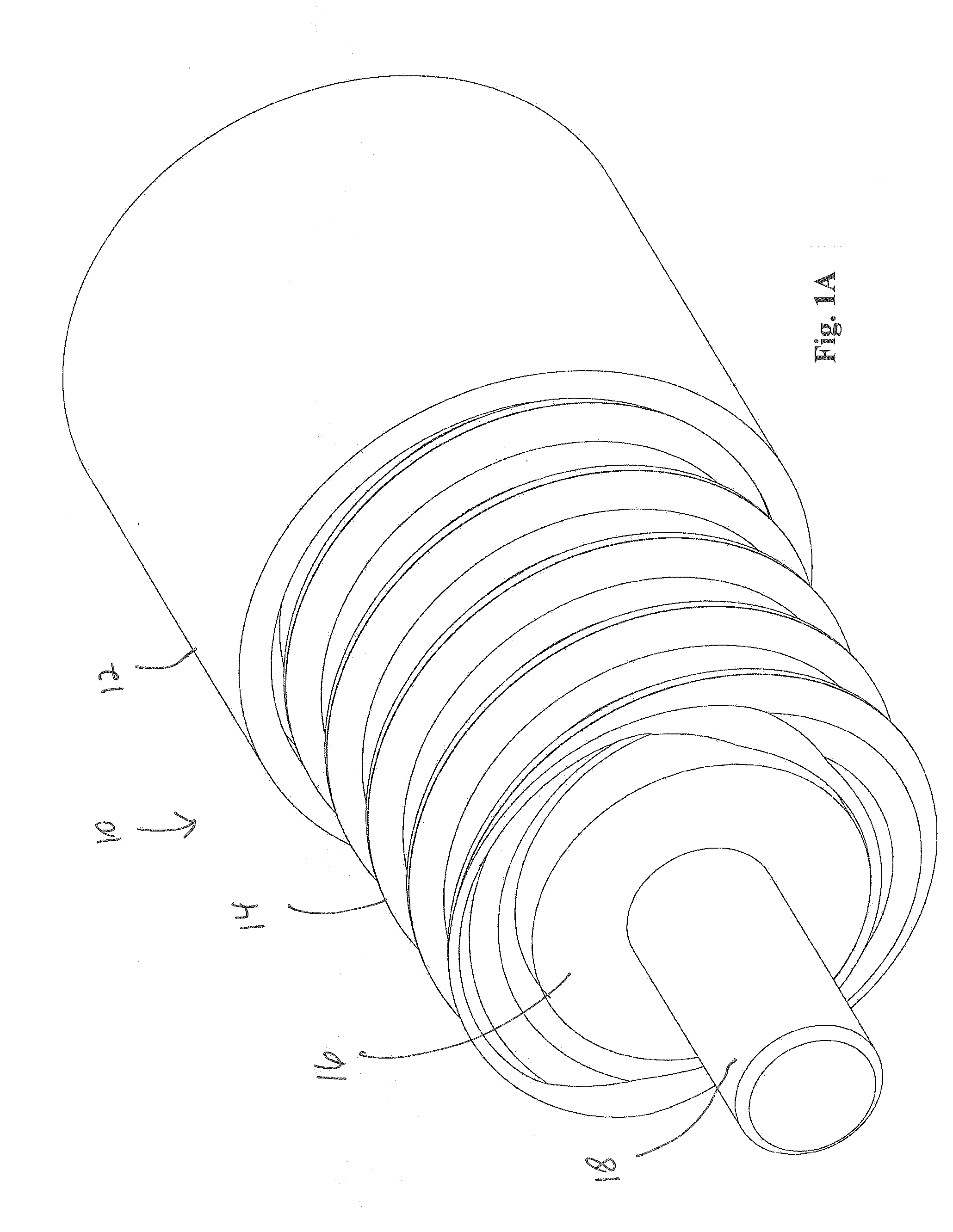
[0033]Referring to FIG. 1A, a spiral corrugated coaxial cable 10 is shown prepared for installation onto a compression connector 20 (FIG. 2). A jacket 12 is cutaway to expose a portion of a spiral corrugated conductor layer 14. Layer 14 is also known as the ground or outer conductor layer. Both corrugated conductor layer 14 and a dielectric 16 are cutaway from a center conductor 18. Preparation of corrugated coaxial cable 10 for installation is well known in the art.

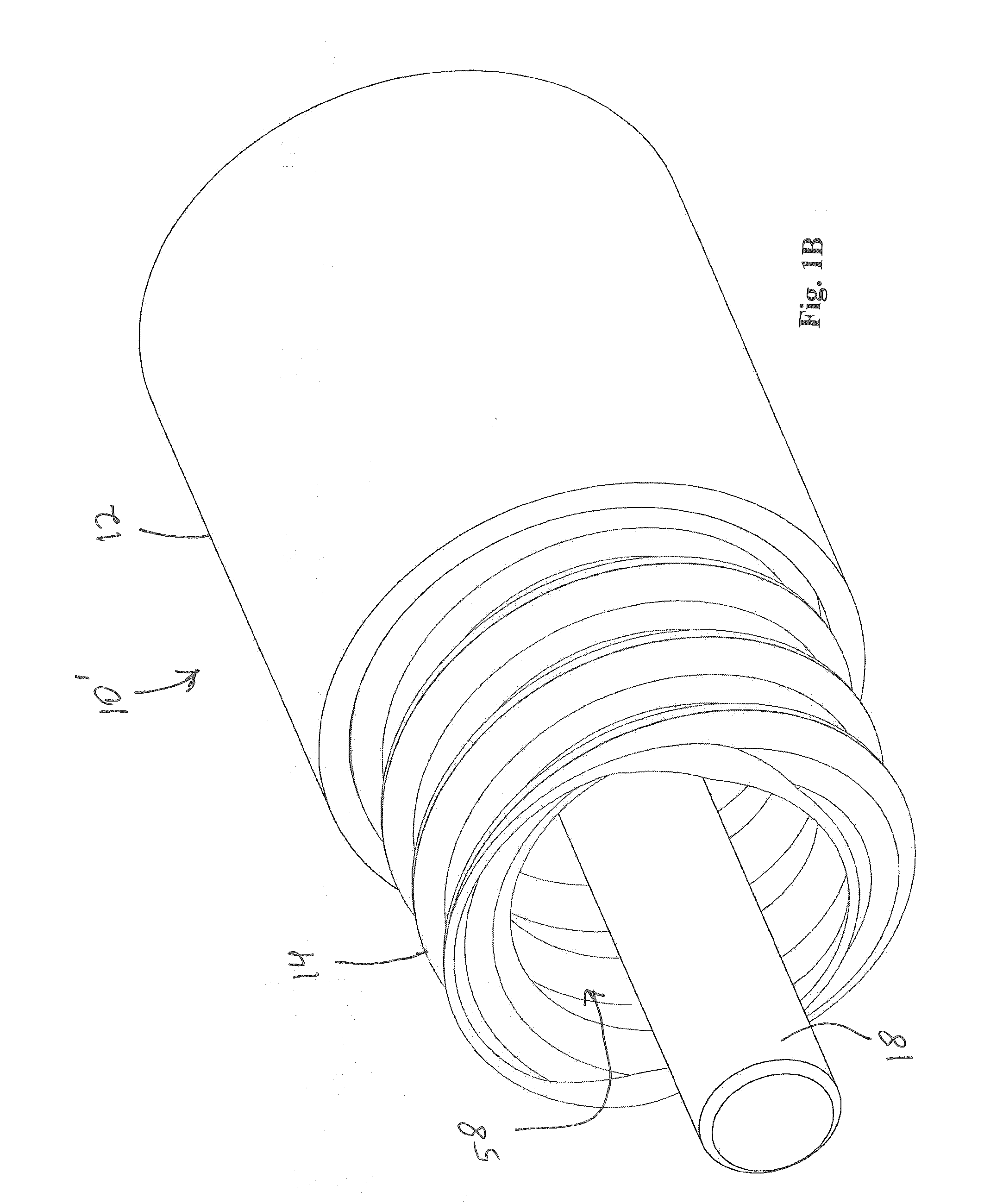
[0034]Referring to FIG. 1B, a spiral corrugated coaxial cable 10′ is shown prepared for installation onto a compression connector 60 (FIG. 6). In addition to jacket 12 being cutaway to expose a portion of spiral corrugated conductor layer 14, dielectric 16 is cored out leaving a hollow 58 after both corrugated conductor layer 14 and dielectric 16 are cutaway from center conductor 18. Preparation of corrugated coaxial cable 10′ for installation is well known in the art.

[0035]Referring to FIG. 1C, a non-spiral corrugated c...


PUM

PropertyMeasurementUnit
Diameteraaaaaaaaaa
Sizeaaaaaaaaaa

Abstract

A compression connector for smooth walled, corrugated, and spiral corrugated coaxial cable includes an insulator disposed within the body, wherein the insulator contains a central opening therein which is dimensioned smaller than a collet portion which seizes a center conductor of the coaxial cable. The connector also includes a clamp disposed inside the body as well as a compression sleeve assembly. An intermediate connector element includes a transitional surface which interacts with the clamp. When an axial force is applied to the compression sleeve, the clamp is forced by the transitional surface into the body, causing the clamp to squeeze onto an outer conductor layer of the coaxial cable. At approximately the same time, the collet portion is forced through the central opening of the insulator, causing the collet portion to squeeze onto the center conductor.

Description

CROSS-REFERENCE TO RELATED APPLICATIONS[0001]This application is a continuation in part of and claims priority from U.S. patent application Ser. No. 11 / 743,633 filed on May 2, 2007 and entitled COMPRESSION CONNECTOR FOR COAXIAL CABLE, incorporated herein by reference.FIELD OF THE INVENTION[0002]This invention relates generally to the field of coaxial cable connectors, and more particularly to a compression connector for smooth walled, corrugated, and spiral corrugated coaxial cable.BACKGROUND OF THE INVENTION[0003]Coaxial cable is installed on a widespread basis in order to carry signals for communications networks such as cable television (CATV) and computer networks. The coaxial cable must at some point be connected to network equipment ports. In general, it has proven difficult to make such connections without requiring labor intensive effort by highly skilled technicians.[0004]These generalized installation problems are also encountered with respect to spiral corrugated coaxial ...

Claims


Application Information

Patent Timeline
IPC IPC(8): H01R9/05H01R43/16
CPCH01R9/0524H01R9/0527Y10T29/49204H01R2103/00H01R24/564
Inventor CHAWGO, SHAWNMONTENA, NOAHPURDY, ERICROBB, DANIAL
Owner JOHN MEZZALINGUA ASSOC INC
Why Eureka
Try Eureka