
Mobile communication network

a mobile communication network and mobile communication technology, applied in the field of mobile communication network using a moving network, can solve the problems of increasing deteriorating the quality of the wireless transmission path of other mobile machines, increasing the power consumption of mobile machine side and network side, etc., to achieve the effect of preventing the increase of the load on the network and power consumption, reducing the frequency of location registration processing conducted over the entirety of the mobile communication network, and reducing the load

Inactive Publication Date: 2009-09-17
FUJITSU LTD
View PDF19 Cites 3 Cited by
  • Summary
  • Abstract
  • Description
  • Claims
  • Application Information

AI Technical Summary

Benefits of technology

The present invention aims to prevent network overload, power consumption, and degraded wireless transmission paths caused by a large number of mobile machines moving on a train or other moving networks. This is achieved by using particular location information to conduct location registration of mobile machines only when they enter a specific area, rather than throughout the entire network. This reduces the frequency of location registration and associated network processing, resulting in improved network performance and reduced power consumption.

Problems solved by technology

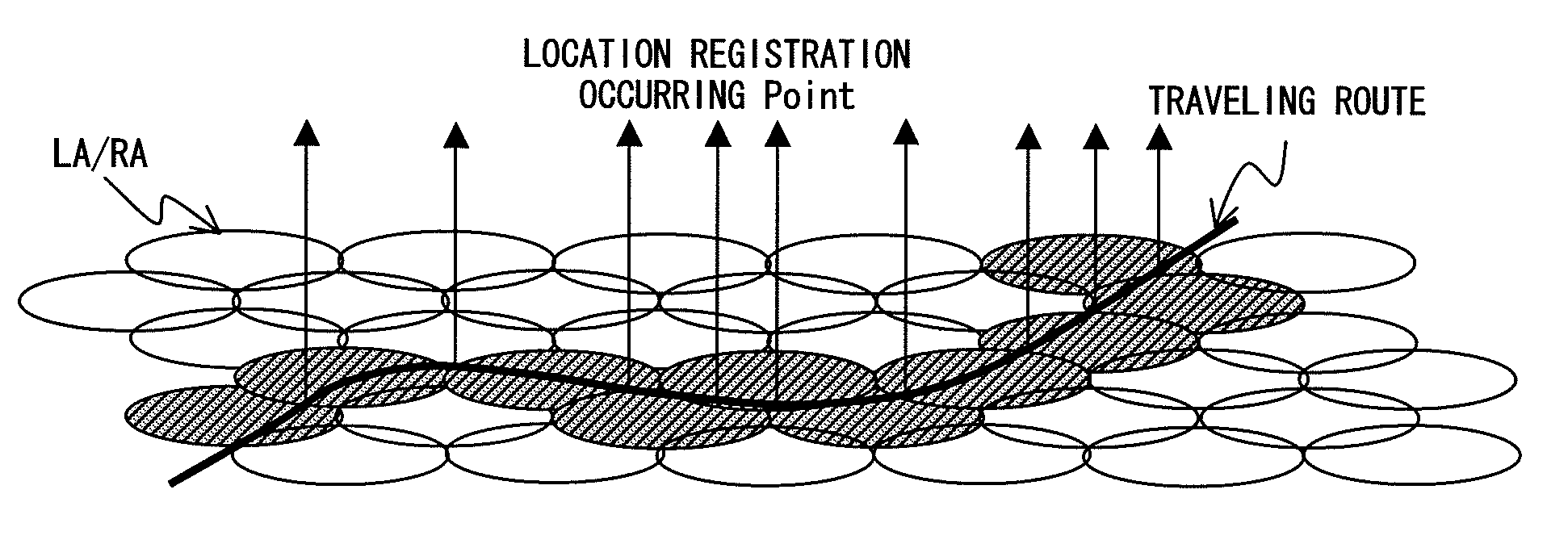
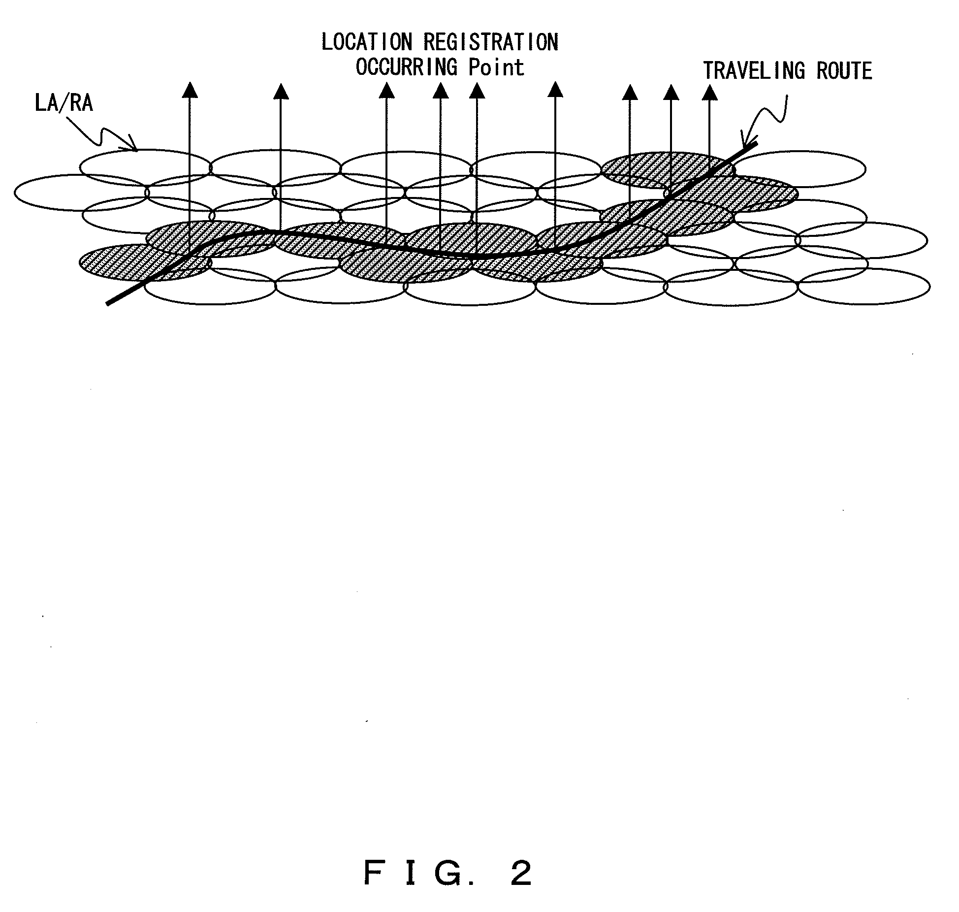
However, in the above techniques there is a problem that when users carrying mobile machines move for a long distance on a public conveyances such as a train, a bus or an airplane, location registration of a large number of mobile machines carried by the users on the conveyances simultaneously occurs inevitably every time as the mobile machines enter in another location registration area.
This problem occurs similarly when users carrying mobile machines move on a speedway on automobiles.
As described above, when users carrying mobile machines move on a train for example, there are three problems.
The first problem is that there is an increased load on a network by location registration accompanied with movement of mobile machines.
The second problem is that the power consumption of mobile machine side and network side is increased by the location registration.
The third problem is that quality of wireless transmission path for other mobile machines is deteriorated due to the location registration.
Accordingly, there occurs an instantaneous increase of load due to these location registrations in the mobile communication network and the core network.
In other words, accompanied with a rapid increase of location registration, quality deterioration of wireless transmission path occurs and power consumption of both of network side and mobile machine side is increased due to the required location registration.
However, the above techniques cannot prevent the increase of the frequency of location registration when a large number of users carrying mobile machines move on a train or the like.
Even in the technique of Japanese unexamined patent application publication No. 11-355835, location registration processings accompanied with the travel of a train are necessary and there is a problem that all of the location information of respective mobile machines have to be updated corresponding to such location registration processings.

Method used


Image

  • Mobile communication network
  • Mobile communication network
  • Mobile communication network

Examples


first embodiment

[0088]Before the explanation of the first embodiment, joining conditions for the moving network of the present embodiment will be explained further. First, there are two preconditions about these joining conditions. The first precondition is that the UE 10 receives the information indicating the existence of the moving network around the UE 10 as the system information from the node B11 side. The second precondition is that the UE 10 can receive the system information added by the moving network device 12 or the information of a pilot channel transmitted from the moving network device 12 by using the contents of the above system information. In the present embodiment, just a satisfaction of these two preconditions satisfies the joining conditions for the moving network.

[0089]Further, as for the joining conditions for the moving network, individual conditions can be added to these preconditions. The first individual condition is that the UE 10 receives the GPS information specifying ...

second embodiment

[0103]Next, the updating of the system information while the UE 10 joins in a moving network will be explained, referring to FIG. 19. In FIG. 5, when updating the system information transmitted from the node B11 side to the UE 10, there are two possible cases i.e. the case where the moving network device 12 concerns the updating and the case where the moving network device 12 does not. The case where the moving network device 12 does not concern will be described later as the second embodiment, and the case where the moving network device 12 concerns is explained here.

[0104]In a case where the system is based on 3GPP as explained in FIG. 11, there can be a configuration in which PCCPCHMN of the moving network, synchronized with PCCPC transmitted from the node B 11 in a chip level is defined and information including the above SIB#n+1 added thereto as moving network individual information is transmitted to the UE 10 side as shown in FIG. 19 so that the UE 10 can receive and also upda...


PUM


Abstract

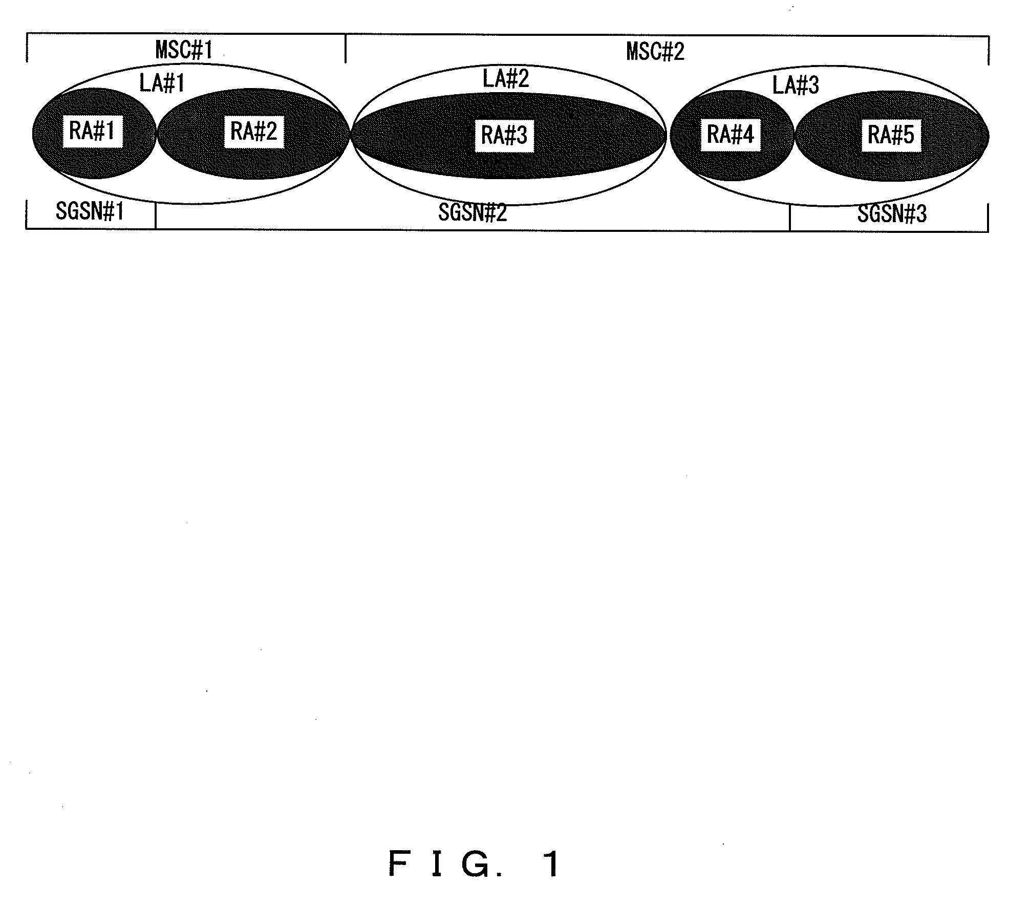
A mobile communication network comprising a plurality of base stations and a plurality of mobile machines, the unit for supplying particular location information assigned to a predetermined particular area in advance to the mobile machines moving in the particular area and the mobile machines conduct location registration to the base station side by using the particular location information at a time when the mobile machine enters in the particular area, thereby, increase of load on a network and of power consumption, and quality deteriorations of transmission paths, due to location registration when many users carrying the mobile machines move on a train or the like can be prevented.

Description

CROSS REFERENCED TO RELATED APPLICATION[0001]This application is a divisional of U.S. application Ser. No. 11 / 002,870 filed on Dec. 2, 2004, now pending and claims priority from Japanese Patent Application 2004-250148 filed on Aug. 30, 2004, the contents of which are herein incorporated by reference.BACKGROUND OF THE INVENTION[0002]1. Field of the Invention[0003]The present invention relates to a method of location registration to base station side conducted by mobile machines in a mobile communication network, and more particularly to a mobile communication network using a moving network, in which, when users carrying mobile machines move on a train or the like, location registration is conducted by using particular location information assigned to a particular area in advance without using conventional location information.[0004]2. Description of the Related Art[0005]In a mobile communication system, when transmission is conducted to a particular mobile machine existing in a servi...

Claims


Application Information

Patent Timeline
Patent Type & Authority Applications(United States)
IPC IPC(8): H04W4/00H04W4/02H04W8/24H04W60/04
CPCH04W4/02H04W60/04H04W8/245H04W88/005
Inventor SHINOZAKI, ATSUSHI
Owner FUJITSU LTD
Learn More