
Exhaust purification system, control apparatus and control method therefor

a technology of exhaust fuel valve and purification system, which is applied in the direction of exhaust treatment electric control, mechanical equipment, machines/engines, etc., can solve the problem of not being able to specify the reason why the exhaust temperature does not rise sufficiently, oxidation catalyst or exhaust fuel valve may have to be replaced unnecessarily,

Inactive Publication Date: 2009-09-24
DENSO CORP
View PDF1 Cites 42 Cited by
  • Summary
  • Abstract
  • Description
  • Claims
  • Application Information

AI Technical Summary

Benefits of technology

[0008]It is therefore an object of the present invention to provide an exhaust purification system, a control apparatus and a control method, which can determine whether an insufficient exhaust temperature rise is caused by abnormality of an exhaust fuel valve or an oxidation catalyst provided in an exhaust passage of an internal combustion engine.

Problems solved by technology

If the exhaust fuel valve is used, the exhaust temperature sometimes does not rise sufficiently even when the exhaust fuel valve is driven to inject the additive fuel into the exhaust passage.
It is not possible to specify the reason why the exhaust temperature does not rise sufficiently, that is, whether the additive fuel does not react in the oxidation catalyst because of failure (abnormality) of the oxidation catalyst in spite of the exhaust fuel valve operating normally, or whether the additive fuel is not supplied because of failure of the exhaust fuel valve in spite of the oxidation catalyst operating normally.
As a result, the oxidation catalyst or the exhaust fuel valve may have to be replaced with a new one unnecessarily to raise the exhaust temperature.

Method used


Image

  • Exhaust purification system, control apparatus and control method therefor
  • Exhaust purification system, control apparatus and control method therefor
  • Exhaust purification system, control apparatus and control method therefor

Examples


Embodiment Construction

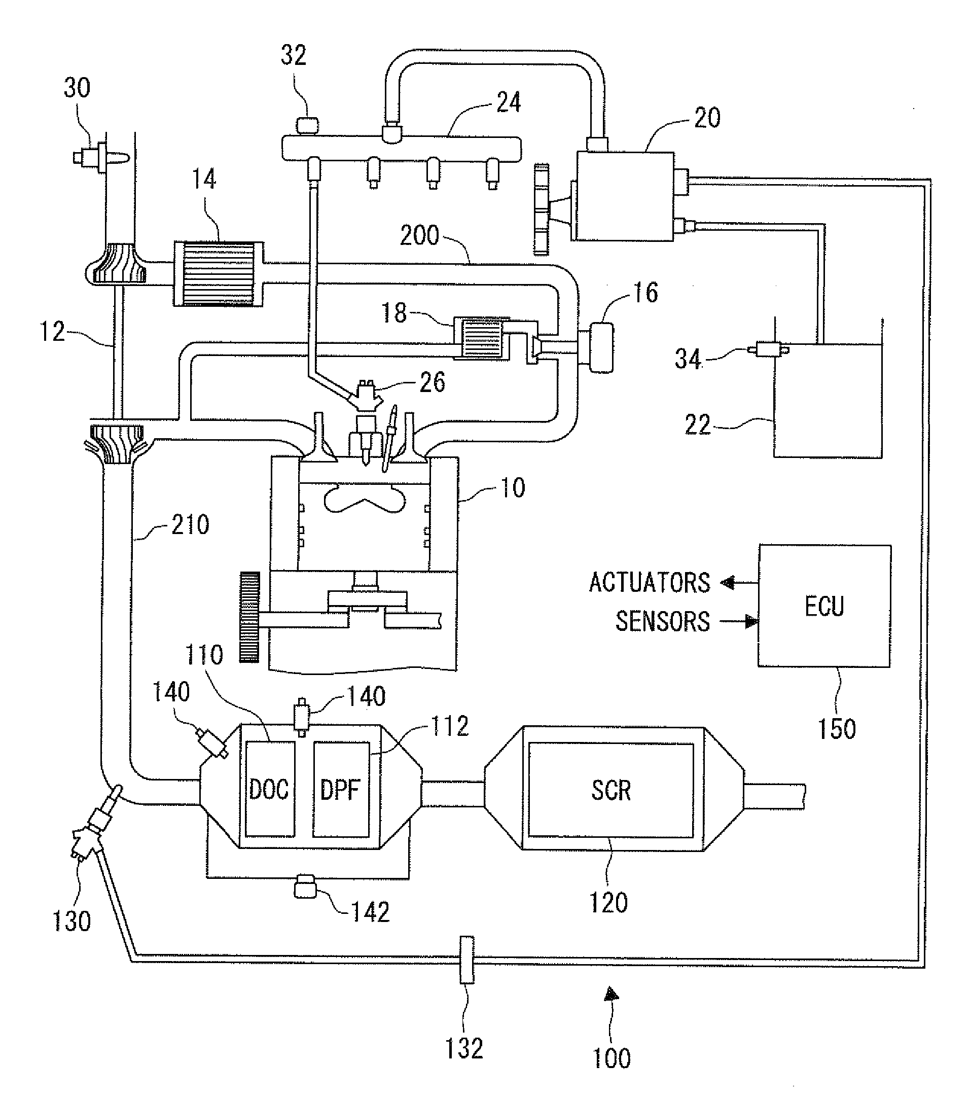
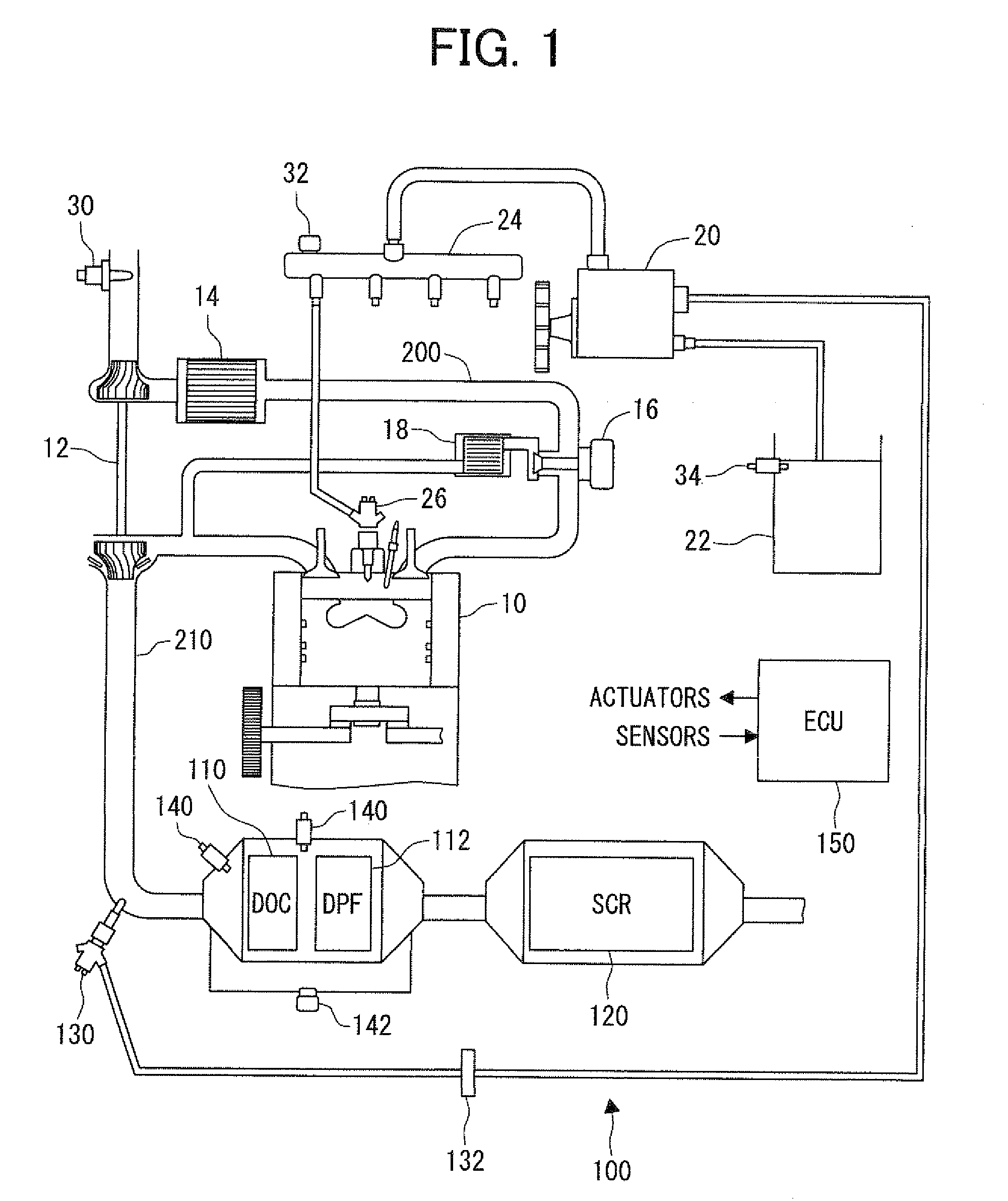
[0014]Referring first to FIG. 1, an exhaust purification system 100 is provided for purifying gas exhausted from a four-cylinder four-stroke diesel engine 10 into an exhaust passage 210.

[0015]The engine 10 has an intake passage 200, in which a turbocharger 12 is provided to supply compressed air and an intercooler 14 for cooling the compressed air before being supplied into the engine 10. The intake passage 200 and the exhaust passage 210 are connected to each other via an exhaust gas recirculation (EGR) passage, which recirculates a part of the exhaust gas of the engine 10 through an EGR cooler 18 and an EGR valve 16 when the EGR valve 16 is opened.

[0016]A fuel supply pump 20, which is a high-pressure pump having a reciprocating plunger, is provided to suction fuel from a fuel tank 22 and pressurize the fuel. The amount of pressurized fuel discharged or supplied from the fuel supply pump 20 is regulated by regulating the amount of fuel suctioned into the pump 20 by a metering valve...


PUM


Abstract

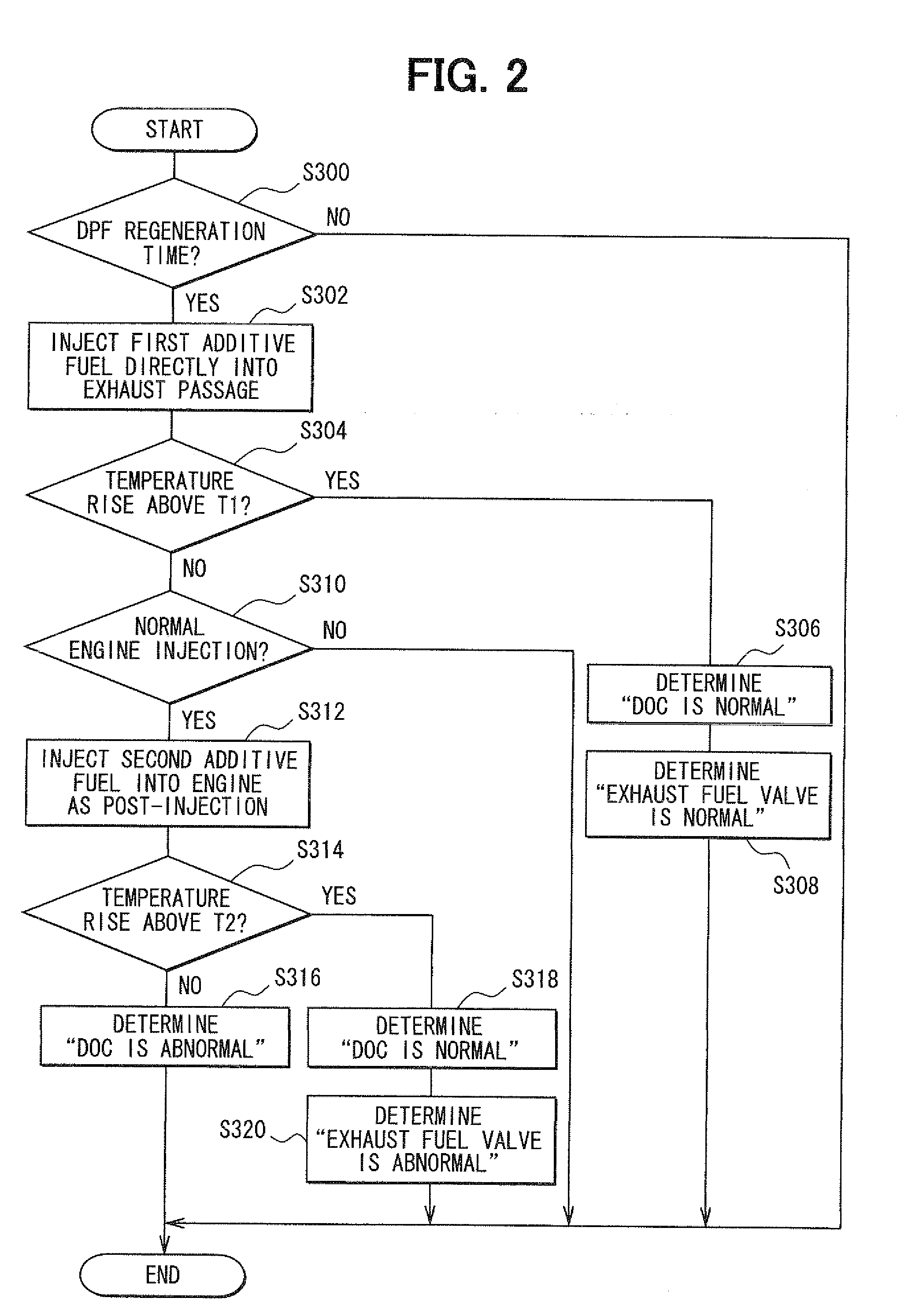
An exhaust gas purification control apparatus for an internal combustion engine instructs an exhaust fuel valve to inject additive fuel when a diesel particulate filter is to be regenerated, and determines that both the exhaust fuel valve and an oxidation catalyst are normal if an exhaust temperature rises. If the exhaust temperature does not rise, the control apparatus instructs an engine fuel valve to inject additive fuel as a post-injection. If the exhaust temperature does not rise, the control apparatus determines that the oxidation catalyst is abnormal. If the exhaust temperature rises, the control apparatus determines that the oxidation catalyst is normal but the exhaust fuel valve is abnormal.

Description

CROSS REFERENCE TO RELATED APPLICATION[0001]This application is based on and incorporates herein by reference Japanese Patent Application No. 2008-76106 filed on Mar. 24, 2008.FIELD OF THE INVENTION[0002]The present invention relates to an exhaust purification system for an internal combustion engine, which includes an oxidation catalyst provided upstream an exhaust purification device in an exhaust passage of an internal combustion engine and an exhaust fuel valve provided to supply additive fuel into the exhaust passage so that exhaust temperature is raised by the oxidation reaction of the additive fuel in the oxidation catalyst, and a control apparatus and a control method for the exhaust purification system.BACKGROUND OF THE INVENTION[0003]In some conventional exhaust purification systems (for example, JP 9-222009A), an oxidation catalyst is provided upstream an exhaust purification device in an exhaust passage of an internal combustion engine so that the exhaust temperature is ...

Claims


Application Information

Patent Timeline
Patent Type & Authority Applications(United States)
IPC IPC(8): F01N9/00
CPCF01N3/035F01N3/2066F01N11/002F01N2550/02F01N13/009F01N2560/06F01N2560/08F01N2560/14Y02T10/47F01N2550/05Y02T10/40
Inventor NODA, YOSHIHIRO
Owner DENSO CORP
Learn More