Circular dividing table for machine tool

a machine tool and dividing table technology, applied in the field of circular dividing tables for machine tools, can solve the problems of limiting the view point of machine design of measures and retardating the action

Inactive Publication Date: 2009-09-24
DMG MORI SEIKI CO LTD
View PDF6 Cites 35 Cited by
  • Summary
  • Abstract
  • Description
  • Claims
  • Application Information

AI Technical Summary

Benefits of technology

[0024]In the fifth aspect of this invention, the circular dividing table for a machine tool in the fourth aspect is so arranged that a preliminary tapered cam face (73) with an inclination angle (γ) larger than said inclination angle (α) of the tapered cam face (72) is additively formed in the front portion of said first tapered

Problems solved by technology

However, said arrangement is not preferable in which the clamping member is released and returned to the original position by a return spring.
This is because of the fact that the action of the arrangement becomes unstable due to the deterioration of the return springs caused by metal fa

Method used


Image

  • Circular dividing table for machine tool
  • Circular dividing table for machine tool
  • Circular dividing table for machine tool

Examples


Embodiment Construction

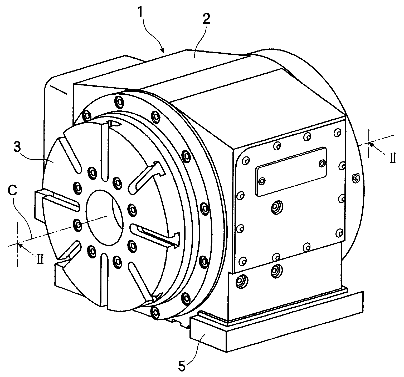
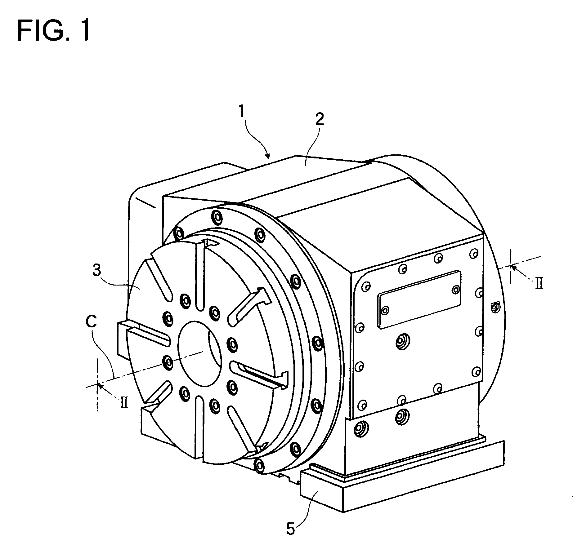
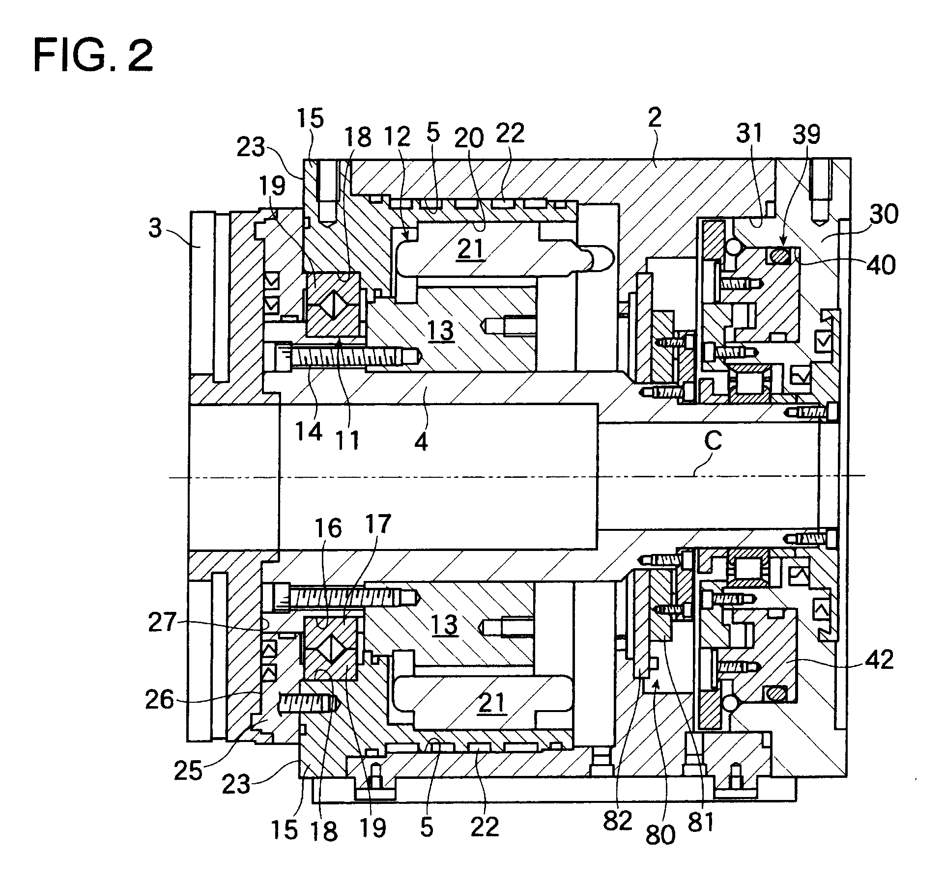
[0032]An embodiment of the circular dividing table for a machine tool according to this invention is shown in FIGS. 1 and 2, of which FIG. 1 shows an external view and FIG. 2 shows a cross-sectional view taken along the line II-II in FIG. 1. The circular dividing table 1 for a machine tool consists of a housing 2, a face plate 3 on which a work to be machined by the machine tool is placed and fixed, a spindle 4 as a support shaft which is supported rotatably in the housing 2, etc. The housing 2 has in its lower portion fixture legs 5 which are arranged so as to be secured by bolts, jigs or the like at the predetermined position on the table of the machine tool.

[0033]The stator fixing flange 15 supports the spindle 4 rotatably with a main bearing (for example a roller bearing). Around the spindle 4 substantially at its center portion, a rotor 13 as a constituent of a DD motor 12 is fitted onto the spindle 4. The rotor 13 is secured by plurality of bolts 14 which are disposed on the c...


PUM


Abstract

By causing the annular piston (42) to be freed, the piston return spring (54) comes to urge the annular piston (42) with the bottom face of its annular groove (50), so that the piston (42) retires backward and the floating pad return plate (62) contacts with the bracket (64) extending inward within the cylindrical bore (61) of the floating pad (60), thus urging the floating pad (60) backward. By the backward displacement of the floating pad (60), the floating pad (60) is forced to be departed from the brake disc (66).
A circular dividing table equipped with such a brake assembly, it is possible to release the clamping members forcibly and to make the action of clamping or unclamping precisely and in a high responsive speed.

Description

FIELD OF THE INVENTION[0001]The present invention relates to a circular dividing table for a machine tool, also called as a swivel table, a swivel slide, a swivel base, a dividing head, an indexed head, a rotary table, a circular table, etc., used in a machine tool such as a machine center and specifically relates to a circular dividing table for a machine tool equipped with a dividing device which is capable of precise alignment of a rotating shaft at predetermined angular positions.BACKGROUND ART[0002]In a circular dividing table for a machine tool, the shaft connected with a circular table and driven by a drive motor must be aligned precisely at a desired angular position and then be clamped by a clamping device. In this regard, an apparatus is known in which a DD(direct drive) motor is used as the drive motor and an electromagnetic brake is provided in place of a friction brake as the clamping device(see Japanese Laid-Open Patent Application 2007-125640, for example).[0003]A fri...

Claims


Application Information

Patent Timeline
IPC IPC(8): B23Q16/10
CPCB23Q16/102B23Q16/105Y10T74/1488Y10T74/1494Y10T74/14B23Q11/127B23Q2220/004
Inventor DUANE, JACOBPINER, ZACHARY
Owner DMG MORI SEIKI CO LTD
Why Eureka
Try Eureka