
Drain grate system and methods

a drain grate and drain system technology, applied in the direction of sewage draining, separation processes, ways, etc., can solve the problems of reducing the drain capacity, affecting the drainage effect, and accumulating litter, etc., to increase the amount of rotation

Inactive Publication Date: 2009-09-24
ALVARADO JOHN
View PDF32 Cites 32 Cited by
  • Summary
  • Abstract
  • Description
  • Claims
  • Application Information

AI Technical Summary

Benefits of technology

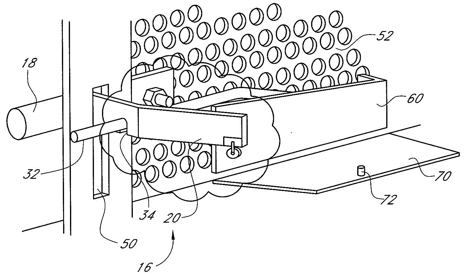
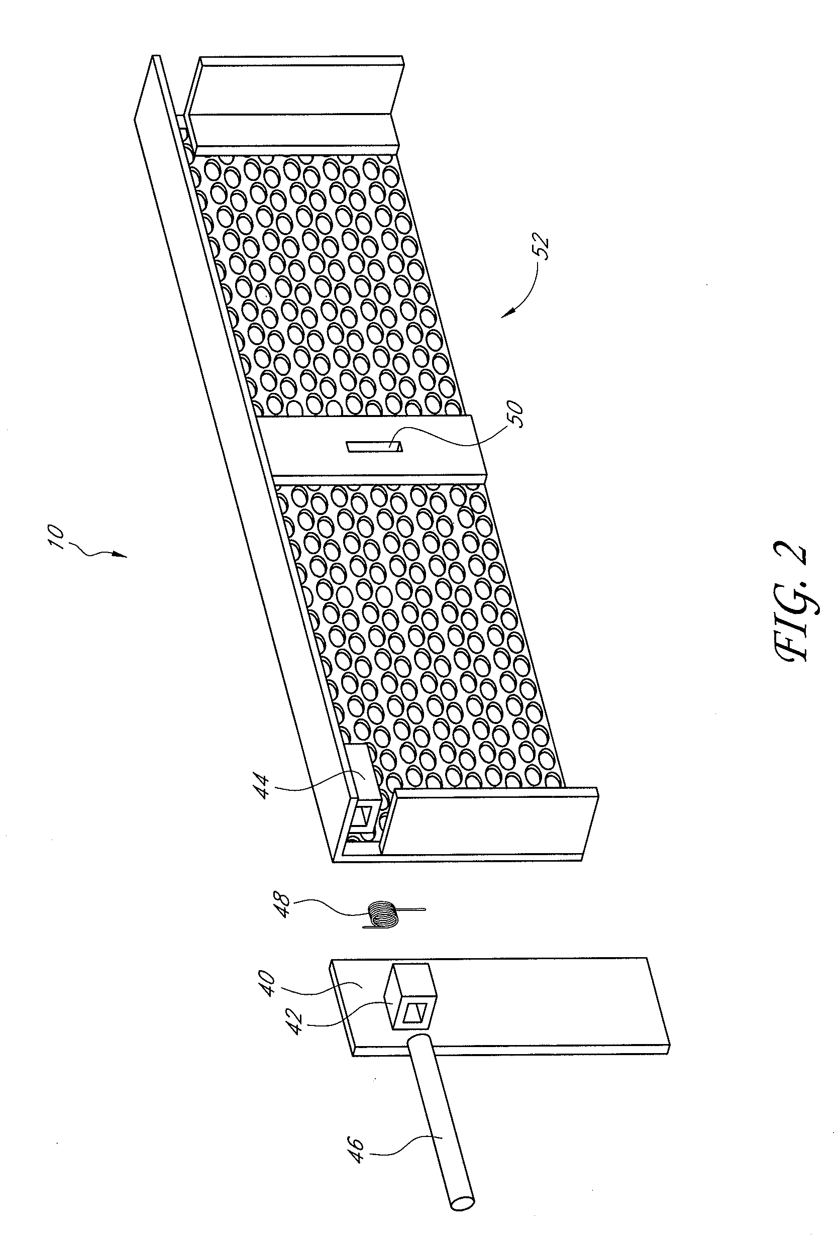
[0014]Some embodiments of a storm drain grate system comprise a gate, first and second force plates and a locking mechanism. The gate can be rotatable between a closed position and an open position and configured to allow fluid flow therethrough while preventing passage of debris of a predetermined size and shape when in the closed position. The first force plate can be configured to rotate about a first axis in a first direction. While the second force plate can be configured to rotate about a second axis in a second direction opposite the first direction, the first axis substantially parallel to the second axis. The first and second force plates can be configured to rotate independently by a predetermined amount of force of a flowing liquid. The locking mechanism can return to a locked position when the gate is in the closed position and the rotation of either or both of the first and second force plates can unlock the locking mechanism and allowing the gate to rotate from the closed position to the open position.
[0019]The storm drain grate locking mechanism of some embodiments can further comprise a second cam configured to increase the displacement of the second interlock portion to thereby increase the amount of rotation experienced by the second interlock portion, a second hinged actuation member and a third interlock portion. Rotation of the second actuation member about a third cam can cause the second actuation member to rotate about an axis while at the same time moving along the axis, the axial displacement causing the third interlock portion to rotate and to contact the second interlock portion thereby disengaging the second interlock portion from the first interlock portion.

Problems solved by technology

In these areas, litter, trash, and other debris such as plant trimmings, leaves, and bark may accumulate on the roadway and be blown or washed towards the drains.
In dry seasons, when the precipitation is not sufficient to flush the drain systems regularly, the debris may accumulate in the drains.
In a subsequent rainy season, the accumulated debris may clog the drain, leading to greatly reduced drain capacity and ultimately road flooding at or near the drain opening.
Additionally, the flow of water through a drain that is clogged or partially clogged with debris is likely to result in the release of some or all of the debris into the flow of water continuing downstream from the drain.
These movable drain grates, while desirably preventing debris accumulation during relatively dry weather and allowing higher flow capacity during high water flow periods, remain prone to flooding in certain high water flow periods.
Since the actuator is operatively connected to the drain grate, the flotation of the actuator closes the drain grate, thereby reducing the flow capacity of the drain opening.
Furthermore, some of the attempted solutions require a relatively deep basin to operate effectively.
Thus, actuators in some of the previous drain grate actuation systems could not be sized to fit a relatively shallow drain basin.
Additionally, various cities and counties have drafted rules and regulations limiting the size of acceptable drain grate systems such that many of the previous designs are no longer acceptable.

Method used


Image

  • Drain grate system and methods
  • Drain grate system and methods
  • Drain grate system and methods

Examples


Embodiment Construction

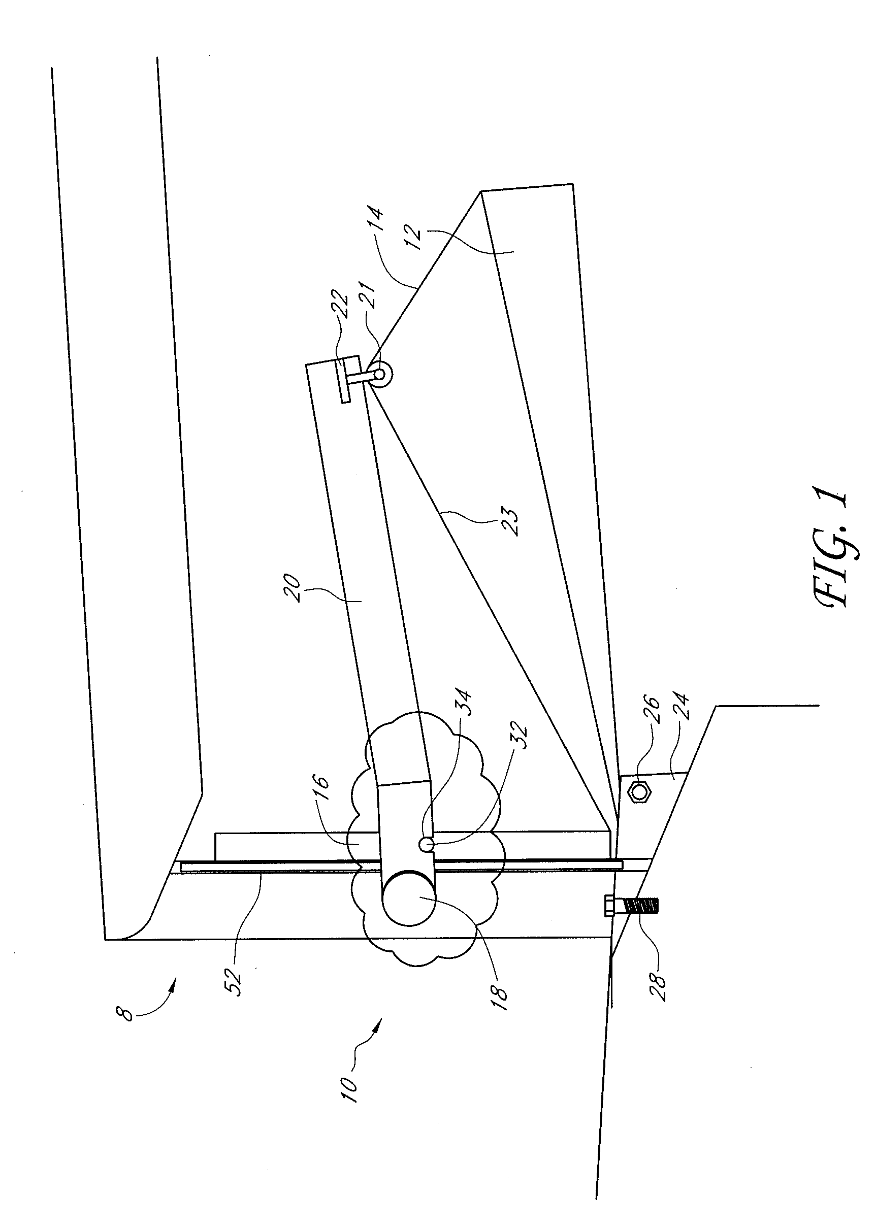
[0029]With reference to FIG. 1, in certain embodiments, a drain grate system 10 is provided comprising a grate 52 connected by a hinge to an opening of a drain 8, and a grate actuator 12 operatively coupled to the grate. The grate 52 is configured to allow the flow of a liquid therethrough and to block passage of debris therethrough. The grate actuator 12 is operatively coupled to the grate 52 such that for small flow rates of liquid through the grate 52, the position of the actuator 12 does not cause the grate 52 to open and for larger flow rates of liquid through the grate 52, the actuator 12 causes the grate 52 to open.

[0030]The drain 8 can be any of the various types of drains, such as storm drains, curb basins, catch basins, etc. The distance from the drain opening to the back of the drain (not shown) varies and can be, for example, between 6″ and 24″ for smaller drains. Other drains can be much longer, for example, 3′ to 6′. The size of the drain opening can also vary. Example...


PUM

PropertyMeasurementUnit
Forceaaaaaaaaaa
Flow rateaaaaaaaaaa
Energyaaaaaaaaaa

Abstract

A drain grate system can be installed in a curbside or storm drain to block the passage of debris while allowing liquid to flow into the drain. The drain grate system can open in response to a high flow rate to allow liquid and debris to flow into the drain. A locking mechanism can maintain the drain grate system in a closed and locked position and can unlock in response to a predetermined amount of force of a fluid flow.

Description

CROSS-REFERENCE TO RELATED APPLICATIONS[0001]This application claims the benefit of U.S. Provisional Application No. 61 / 037,673 filed Mar. 18, 2008, the entirety of which is incorporated herein by reference.BACKGROUND OF THE INVENTION[0002]1. Field of the Invention[0003]The application relates generally to the field of street drainage, more specifically to drain grates that are movable in response to water flow therethrough.[0004]2. Description of the Related Art[0005]Road drainage systems such as curb-integrated storm drains are common throughout urban and suburban areas. In these areas, litter, trash, and other debris such as plant trimmings, leaves, and bark may accumulate on the roadway and be blown or washed towards the drains. In dry seasons, when the precipitation is not sufficient to flush the drain systems regularly, the debris may accumulate in the drains.[0006]In a subsequent rainy season, the accumulated debris may clog the drain, leading to greatly reduced drain capacit...

Claims


Application Information

Patent Timeline
IPC IPC(8): E03F5/14B01D21/34
CPCE03F1/00E03F5/046E03F5/0404
Inventor ALVARADO, JOHN
Owner ALVARADO JOHN
Learn More