Synchronous rectifying DC-DC converter

a dc-dc converter and synchronous technology, applied in the direction of dc-dc conversion, climate sustainability, power conversion systems, etc., can solve the problems of difficult conventional dead time control methods, little time available for dead time control, and perform dead time control. , to achieve the effect of adapting to the effect of being prevented from being turned

Active Publication Date: 2009-09-24
TDK CORPARATION
View PDF2 Cites 18 Cited by
  • Summary
  • Abstract
  • Description
  • Claims
  • Application Information

AI Technical Summary

Benefits of technology

[0015]According to the present invention, the allowable margin of dead time that is specific to a synchronous rectifying DC-DC converter can be identified and, in a critical situation in which a commutating transistor cannot be t

Problems solved by technology

In such a high-frequency range, there will be little time available for dead time control.
It is very difficult for the conventio

Method used


Image

  • Synchronous rectifying DC-DC converter
  • Synchronous rectifying DC-DC converter
  • Synchronous rectifying DC-DC converter

Examples


Embodiment Construction

[0020]An embodiment of the present invention will be described with reference to the accompanying drawings.

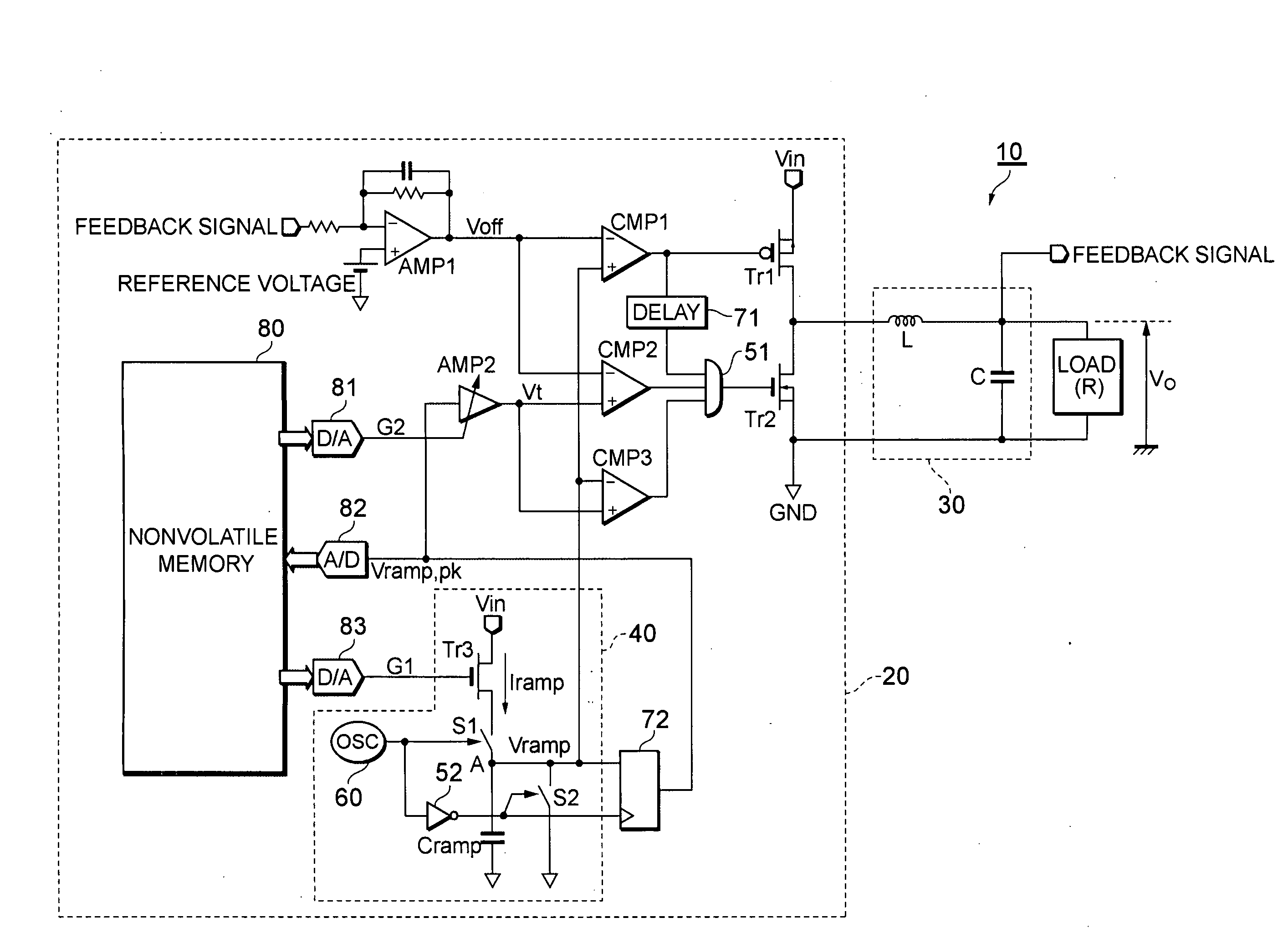
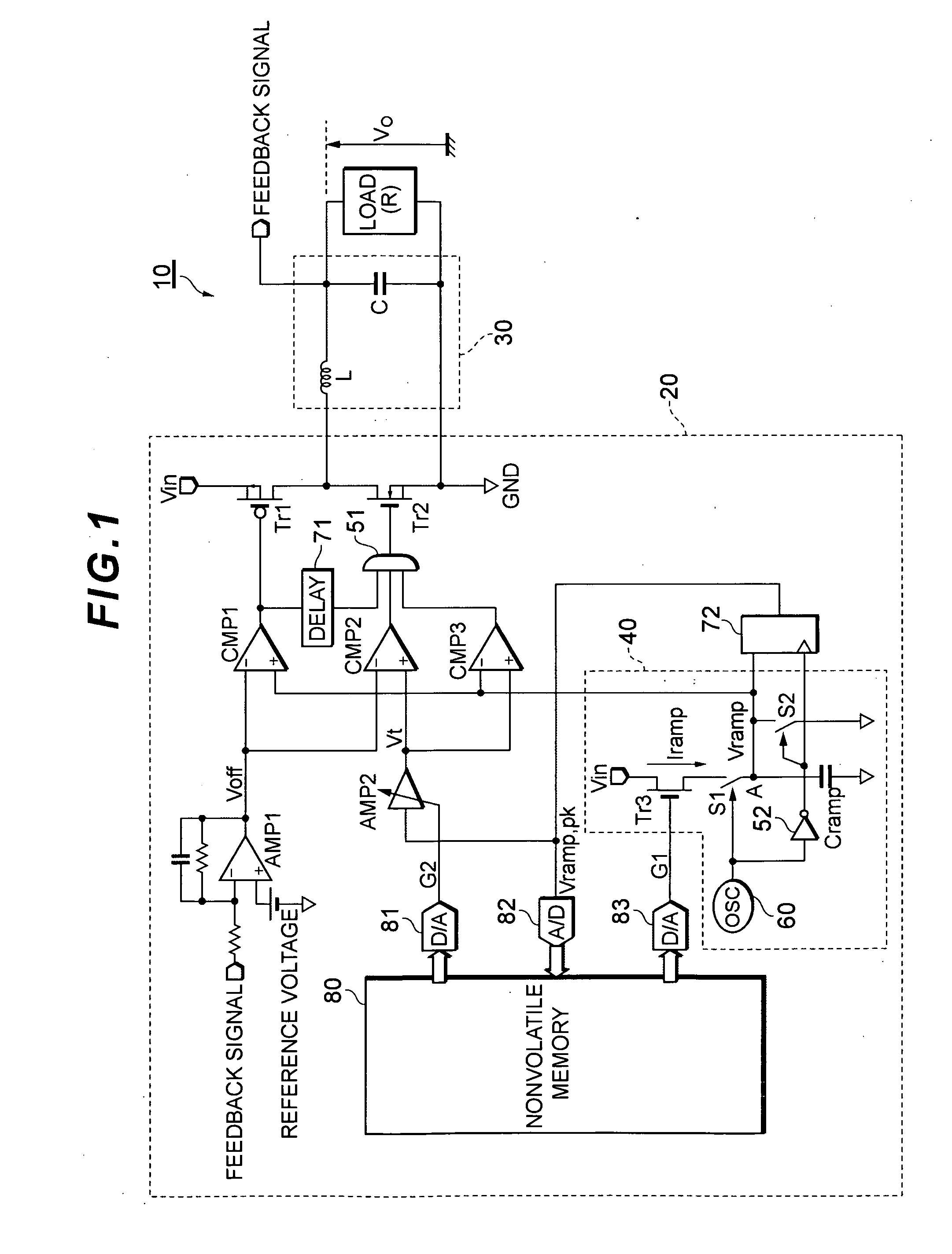
[0021]A synchronous rectifying DC-DC converter 10 according to an embodiment of the present invention is a step-down converter for decreasing an input voltage Vin supplied from a source such as a battery to a desired output voltage Vo to supply the operating voltage Vo to a load R. The synchronous rectifying DC-DC converter 10 includes a power-supply control circuit 20 which outputs a pulsed voltage that is duty-cycle-controlled in accordance with the ratio between the input voltage Vin and the output voltage Vo and a smoothing circuit 30 which smoothes the pulsed voltage to supply the DC voltage Vo to the load R. The power-supply control circuit 20 includes a switching transistor Tr1, a commutating transistor Tr2, a ramp generator 40, an error amplifier AMP1, a variable amplifier AMP2, comparators CMP1, CMP2, and CMP3, an AND circuit 51, a logic inverter 52, a delay circuit 71...


PUM


Abstract

There is provided a dead time control method capable of recognizing a critical situation in which a commutating transistor cannot be turned on because of a temporary variation in an output voltage of a synchronous rectifying DC-DC converter and adaptively preventing the commutating transistor from being turned on. The synchronous rectifying DC-DC converter compares an output Voff of an error amplifier with a voltage Vt obtained by multiplying the peak voltage of a ramp by G2. When Voff becomes greater than or equal to Vt, the converter determines that dead time is insufficient to control the switching of the commutating transistor and prevents the commutating transistor from being turned on.

Description

BACKGROUND OF THE INVENTION[0001]1. Field of the Invention[0002]The present invention relates to a synchronous rectifying DC-DC converter and, in particular, to dead time control suitable for high-frequency switching.[0003]2. Description of the Related Art[0004]As portable devices become multifunctional, more and more power supply circuits with different operating voltages are incorporated into the portable devices. For example, a cellular phone includes power supplies such as those for a baseband IC, LCD driver, and power amplifier module with different operating voltages. As power supply circuits for converting a voltage supplied from a battery to an operating voltage of each power supply circuit, synchronous rectifying DC-DC converters have been known in which a switching transistor and a commutating transistor are connected in series between an input power supply and a ground and are turned on and off in a complementary manner to supply a DC voltage to a capacitor of a smoothing...

Claims


Application Information

Patent Timeline
IPC IPC(8): G05F1/00
CPCY02B70/1466H02M3/1588Y02B70/10
Inventor CHIBA, HIRONORI
Owner TDK CORPARATION
Why Eureka
Try Eureka