Eureka AIR delivers breakthrough ideas for toughest innovation challenges, trusted by R&D personnel around the world.

Alarm System and Alarm Method for Vehicle

Active Publication Date: 2009-09-24
TOYOTA JIDOSHA KK
View PDF8 Cites 26 Cited by
  • Summary
  • Abstract
  • Description
  • Claims
  • Application Information

AI Technical Summary

Benefits of technology

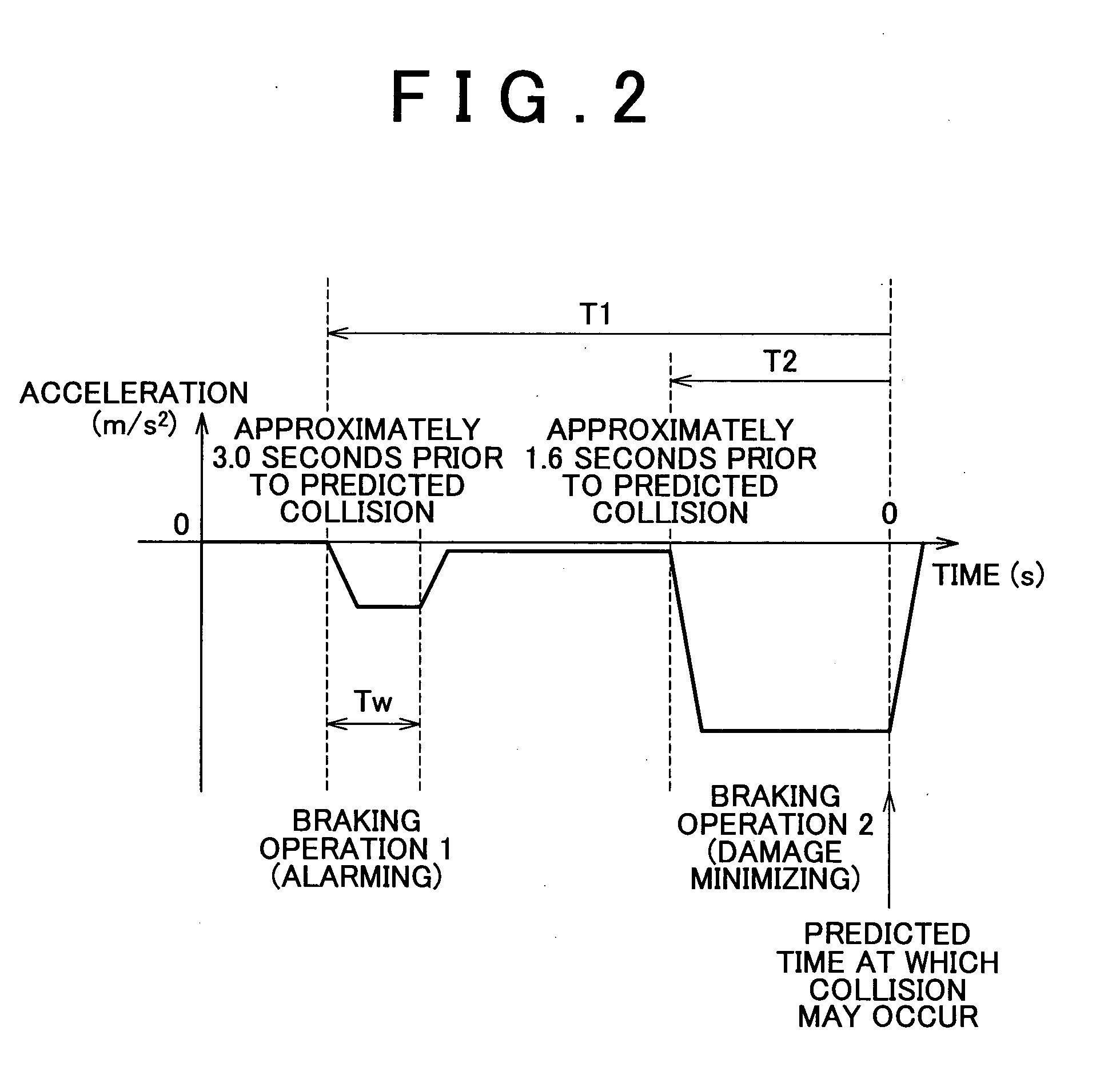
[0009]Accordingly, even if the host vehicle is accelerating immediately before the alarming braking operation is started, it is possible to prevent an amount of change in the acceleration between before and after the alarming braking operation is started from being excessively large, because the target acceleration is set to an appropriate value based on the acceleration of the host vehicle immediately before the alarming braking operation is started. It is, therefore, possible to prevent an excessively large impact from being given to the driver. In addition, even if the host vehicle is running at a constant speed or decelerating immediately before the alarming braking operation is started, it is possible to prevent an amount of change in the acceleration between before and after the alarming braking operation is started from being excessively small because the target acceleration is set to an appropriate value based on the acceleration of the host vehicle immediately before the alarming braking operation is started. As a result, the driver reliably recognizes that the alarming braking operation is performed.
[0011]With the structure described above, the drive power is set to the value at which a negative acceleration is applied to the host vehicle (for example, the engine braking state is realized) so that the target acceleration that is set based on the acceleration of the host vehicle, which is detected when the collision probability index value reaches the predetermined threshold value, is achieved. In addition, the braking force is set so that the target acceleration is achieved. When the drive power for accelerating the host vehicle is generated, it is not necessary to apply a braking force that overcomes the drive power. Accordingly, it is possible to prevent generation of an unnecessary drive power.
[0015]In such a case, if the amount of change in the acceleration of the host vehicle between before and after the alarming braking operation is started is uniform, the higher the acceleration of the host vehicle, which is detected immediately before the alarming braking operation is started, is, the larger the amount of decrease in the acceleration, which is caused by changing the drive power to the value at which the resistance to running of the host vehicle is generated, is. Accordingly, the higher the acceleration of the host vehicle, which is detected immediately before the alarming braking operation is started, is, the smaller the braking force required during the alarming braking operation is. Accordingly, the amount of change in the acceleration, which is caused when the braking force is made 0 when the alarming braking operation ends, becomes smaller, and the effect of giving an alarm to the driver using the impact generated by the difference in the acceleration between before and after the alarming braking operation also becomes smaller.
[0018]If the acceleration of the host vehicle immediately before the alarming braking operation is started is sufficiently high, the impact given to the driver by the alarming braking operation is sufficiently large (namely, there is a sufficiently large difference between the acceleration achieved by setting the drive power for driving the vehicle to the value at which the resistance to running of the host vehicle is generated when the alarming braking operation is started and the acceleration immediately before the alarming braking operation is started). Accordingly, even if the acceleration does not change when the braking force is made 0 at the end of the alarming braking operation, a sufficient effect is produced. In such a case, if the target acceleration is set to a value lower than the acceleration achieved at the drive power for driving the vehicle, at which the resistance to running of the host vehicle is generated, an unnecessary braking force is generated for the alarming braking operation, and the driver may feel a sense of discomfort in the operation of the host vehicle. Accordingly, it is appropriate to set the target acceleration to the acceleration that is achieved at the drive power for driving the host vehicle, at which the resistance to running of the host vehicle is generated, as described above. Thus, it is possible to perform the appropriate alarming braking operation while preventing application of an unnecessary braking force.
[0021]Because the amount of change in the acceleration between before and after the alarming braking operation is started is uniform, the impact given to the driver is also uniform. As a result, it is possible to prevent the situation where the driver feels a sense of discomfort in the operation of the host vehicle because the amount of change in the acceleration is excessively large. It is also possible to prevent the situation where only a small effect is produced because the amount of change in the acceleration is excessively small.

Problems solved by technology

As a result, various inconveniences are caused.
For example, if a braking force is applied to the host vehicle so that the preset negative acceleration is achieved while the host vehicle is accelerating, the driver may feel a sense of discomfort in the operation of the host vehicle because the difference in the acceleration between before and after issuance of an alarm is excessively large.
On the other hand, if a braking force is applied to the host vehicle so that the preset negative uniform acceleration is generated while the host vehicle is decelerating, only a small effect may be produced by the braking operation for giving an alarm to the driver, because the difference in the acceleration between before and after issuance of the alarm is excessively small.

Method used


Image

  • Alarm System and Alarm Method for Vehicle
  • Alarm System and Alarm Method for Vehicle
  • Alarm System and Alarm Method for Vehicle

Examples


Embodiment Construction

[0044]In the following description, the present invention will be described in more detail in terms of an example embodiment.

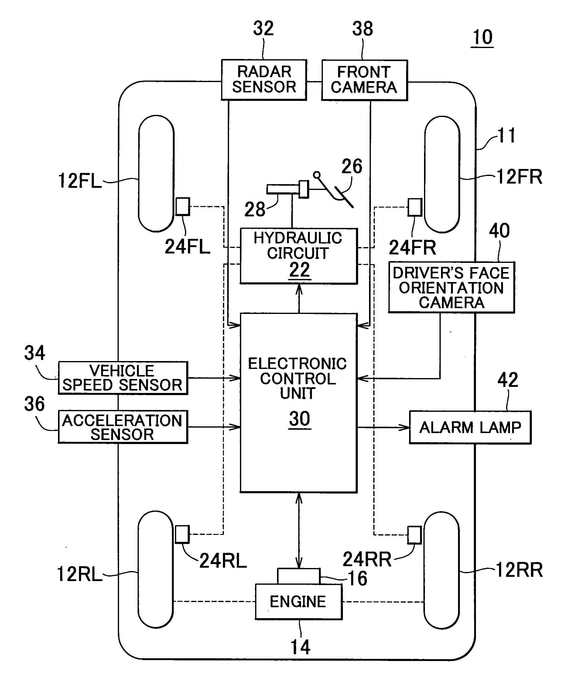
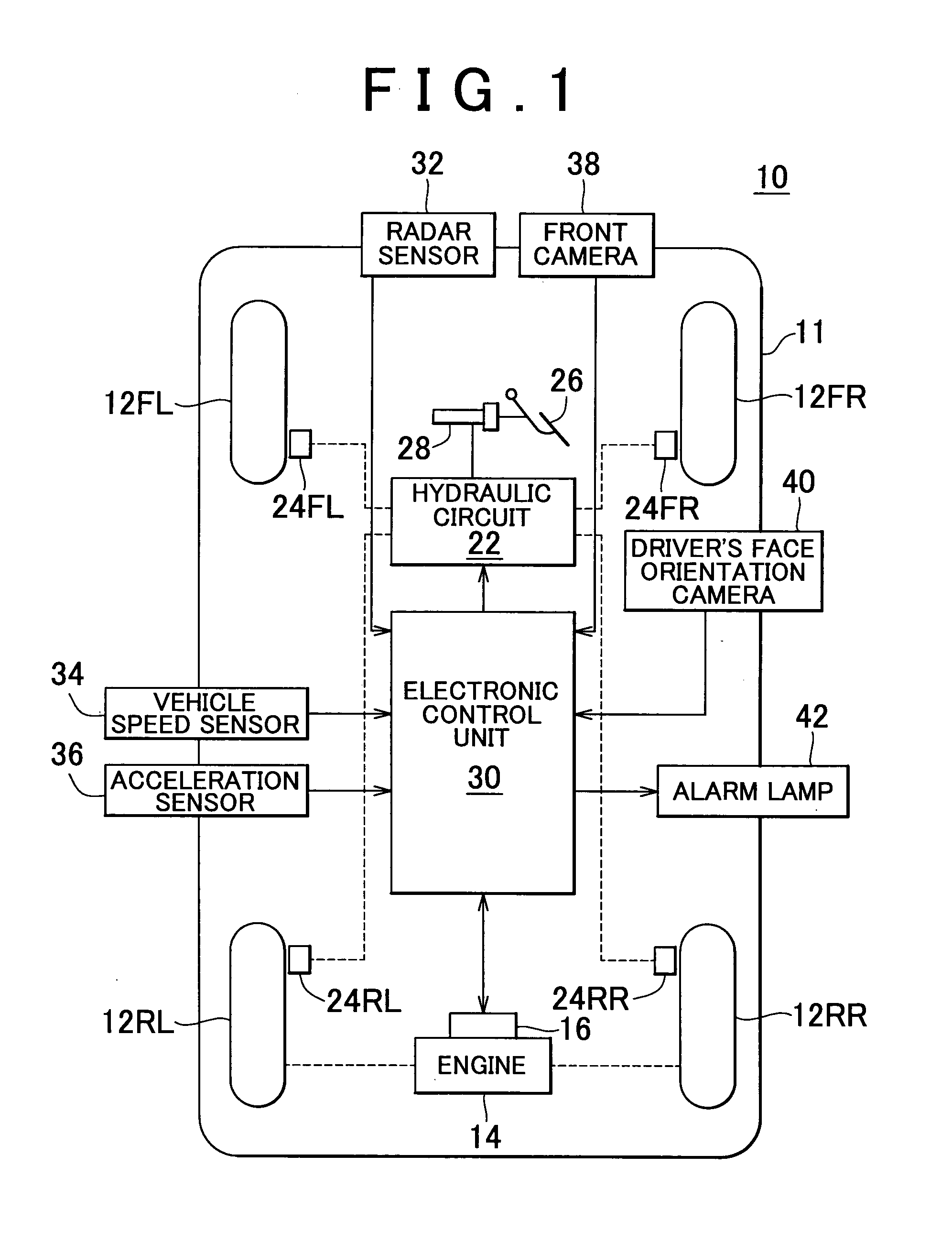
[0045]Hereafter, an alarm system 10 for a vehicle according to an embodiment of the invention will be described with reference to the accompanying drawings. FIG. 1 is the view schematically showing the structure of the alarm system 10 for a vehicle.

[0046]The alarm system 10 for a vehicle (hereinafter, simply referred to as the “alarm system 10”) is mounted in a host vehicle 11. The host vehicle 11 includes a right front wheel 12FR, a left front wheel 12FL, a right rear wheel 12 RR, a left rear wheel 12RL, an engine 14, a throttle valve actuator 16 that drives a throttle valve of the engine 14, a hydraulic circuit 22, a right front wheel cylinder 24FR, a left front wheel cylinder 24FL, a right rear wheel cylinder 24RR, a left rear wheel cylinder 24RL, a brake pedal 26, and a master cylinder 28.

[0047]The alarm system 10 includes an electronic control unit (herei...


PUM


Abstract

A collision probability index value corresponding to a probability of collision between a host vehicle and an obstacle is calculated based on the information indicating the relative relationship between the host vehicle and the obstacle; and the alarming braking operation is performed to cause a driver to recognize that a collision may occur by changing at least one of the drive power and the braking force when the collision probability index value reaches a predetermined threshold value. In the alarming braking operation, a target acceleration that is used as a target value in the alarming braking operation is set based on the acceleration of the host vehicle, which is detected when the collision probability index value reaches the predetermined threshold value; and at least one of the drive power and the braking force is controlled so that the target acceleration is achieved.

Description

BACKGROUND OF THE INVENTION[0001]1. Field of the Invention[0002]The invention relates to an alarm system and method for a vehicle that gives an alarm to a driver by changing the acceleration of a host vehicle in order to avoid a collision between the host vehicle and an obstacle and to minimize damage that will be caused by such a collision.[0003]2. Description of the Related Art[0004]A conventional alarm system for a vehicle gives an impact to a driver by applying a braking force to a host vehicle if it is determined that there is a high probability of collision based on the relative distance and relative speed between the host vehicle and an obstacle, which are input in the host vehicle, thereby giving an alarm to the driver in order to avoid a collision between the host vehicle and the obstacle. If it is determined that there is a high probability of collision, such alarm system for a vehicle applies a braking force to the host vehicle so that the acceleration of the host vehicle...

Claims


Application Information

Patent Timeline
IPC IPC(8): B60Q1/00B60R1/00B60R11/04B60R21/00B60T7/12B60W10/04B60W10/06B60W10/18B60W10/188B60W10/20B60W30/00B60W30/09B60W30/095B60W50/14B60W50/16G08G1/16
CPCB60R21/0134B60W2040/0818B60W10/184
Inventor OKITA, TOSHINORI
Owner TOYOTA JIDOSHA KK
Why Eureka
Eureka Blog
Learn More