Gas storage device for carbon dioxide oil displacement

A carbon dioxide and gas storage device technology, applied in fixed-capacity gas storage tanks, climate sustainability, other gas emission reduction technologies, etc., can solve problems affecting the service life of gas storage devices, increasing costs, and affecting the strength of storage tank steel. , to achieve the effect of unaffected steel strength

Inactive Publication Date: 2021-12-17
DESHI ENERGY TECH GRP CO LTD +1
View PDF7 Cites 0 Cited by
  • Summary
  • Abstract
  • Description
  • Claims
  • Application Information

AI Technical Summary

Problems solved by technology

[0003] When the system is running, it is found that the pressure in the storage tank drops quickly and recovers slowly. When the pressure suddenly drops to a low state and cannot recover quickly, the liquid carbon dioxide will easily condense into dry ice in the storage tank. The sudden drop in temperature in the tank will affect the strength of the steel in the storage tank. Even if other methods are used to liquefy the dry ice in the storage tank later, the damage to the strength of the steel in the storage tank will be irreversible, which in turn will affect the service life of the gas storage device; second, Dry ice will occupy the space in the storage tank, reduce the space of the storage tank cavity, reduce the gas storage and gas supply capacity of the gas storage device, and even dry ice may cause blockage of the outlet or inlet, resulting in the inability of the gas storage device to enter and exit carbon dioxide; Third, due to the large difference between the pressure in the storage tank under normal conditions and the pressure at the inlet of the injection device, the injection device needs a large starting power to change the pressure change. If the pressure in the storage tank recovers slowly, the injection device will have to wait for the storage tank Only when the pressure in the tank returns to a normal state can the pump continue to run, resulting in a blank period for feeding carbon dioxide, which affects the work progress, or, the injection device uses a greater starting power to eliminate the above blank period, but such improvement will The startup power consumption of the injection device is increased, the cost is increased, and the actual application is unrealistic

Method used


Image

  • Gas storage device for carbon dioxide oil displacement
  • Gas storage device for carbon dioxide oil displacement
  • Gas storage device for carbon dioxide oil displacement

Examples


Embodiment approach

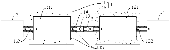
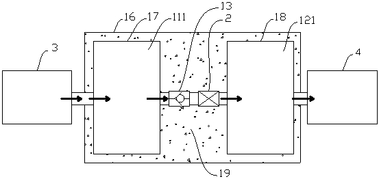
[0040] Such as Figure 1 to Figure 4 As shown, the present invention provides a gas storage device for carbon dioxide flooding, including a storage tank 1, the storage tank 1 includes a first tank body 11 with a first storage cavity 111 and a second tank body with a second storage cavity 121 12. There is a first valve 13 between the first storage chamber 111 and the second storage chamber 121 to control the on-off of the two. The first tank body 11 is provided with a fluid inlet 112 communicating with the first storage chamber 111. The fluid inlet 112 The second tank body 12 is provided with a fluid outlet 122 communicating with the second storage chamber 121, and the fluid outlet 122 communicates with the injection device 4 arranged outside the storage tank 1 , a gas storage device for carbon dioxide flooding is also provided with a pressure regulating device 2, by means of the pressure regulating device 2, the pressure in the second storage chamber 121 can be closer to that ...

Embodiment approach 1

[0047] Implementation mode one: if figure 1 and image 3 As shown, the pressure regulating device 2 is a supercharger arranged between the first storage chamber 111 and the second storage chamber 121 , and the supercharger is connected in series with the first valve 13 .

[0048] In this embodiment, a supercharger is set between the first storage chamber 111 and the second storage chamber 121 as the pressure regulating device 2, and the supercharger cooperates with the first valve 13 to form a The one-way pressurization device, on the one hand, the action force of the supercharger is fast, which can quickly increase the pressure of carbon dioxide between the first storage chamber 111 and the second storage chamber 121, greatly shortening the pressurization process, and further reducing The length of the idle period during which the injection device 4 starts. On the other hand, in the prior art, a supercharging device is added at the gas outlet of the gas storage device. Afte...

Embodiment approach 2

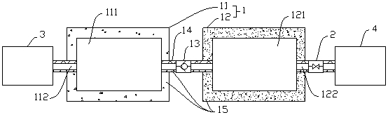
[0050] Implementation mode two: if figure 2 and Figure 4 As shown, the pressure regulating device 2 is a back pressure valve arranged between the second storage chamber 121 and the injection device 4. The back pressure valve is provided with a pressure value close to the pressure at the inlet end of the injection device 4. The second storage chamber 121 When the pressure is greater than or equal to the pressure value, the back pressure valve is opened to connect the second storage chamber 121 with the injection device 4 .

[0051] A back pressure valve is set between the second storage chamber 121 and the injection device 4 as the pressure regulating device 2, which is different from Embodiment 1. In this embodiment, the pressure regulating device 2 is arranged downstream of the second storage chamber 121, and the back pressure valve is set There is a pressure value close to the pressure at the inlet of the injection device 4. When the carbon dioxide in the first storage ch...


PUM


Abstract

The invention relates to the technical field of oil and gas field development and application, and discloses a gas storage device for carbon dioxide oil displacement. The gas storage device comprises a storage tank, the storage tank comprises a first tank body with a first storage cavity and a second tank body with a second storage cavity, a first valve for controlling the first storage cavity and the second storage cavity to be connected and disconnected is arranged between the first storage cavity and the second storage cavity, the first tank body is provided with a fluid inlet communicating with the first storage cavity, the fluid inlet communicates with a supply device arranged outside the storage tank and used for providing carbon dioxide, the second tank body is provided with a fluid outlet communicating with the second storage cavity, and the fluid outlet communicates with an injection device arranged outside the storage tank; the gas storage device for carbon dioxide oil displacement is further provided with a pressure adjusting device, and by means of the pressure adjusting device, the pressure in the second storage cavity can be closer to the pressure of the inlet end of the injection device compared with the pressure in the first storage cavity. The pressurization action on the carbon dioxide occurs in the storage tank, so that the pressure in the storage tank can be rapidly increased, and the curing phenomenon of the carbon dioxide in the storage tank is prevented.

Description

technical field [0001] The invention relates to the technical field of oil and gas field development and application, in particular to a gas storage device for carbon dioxide flooding. Background technique [0002] Carbon dioxide flooding technology is to inject carbon dioxide into the oil layer through the injection device to improve the oil recovery rate of the oil field. In the prior art, a gas storage device for carbon dioxide flooding is provided before the injection end of the injection device, and the gas storage device for carbon dioxide flooding includes a storage tank, which is used to store low-temperature and high-pressure liquid carbon dioxide, and can be continuously injected into the injection device. Provide carbon dioxide. [0003] When the system is running, it is found that the pressure in the storage tank drops quickly and recovers slowly. When the pressure suddenly drops to a low state and cannot recover quickly, the liquid carbon dioxide will easily co...

Claims


Application Information

Patent Timeline
Patent Type & Authority Applications(China)
IPC IPC(8): F17C7/00F17C13/04F17C13/02E21B43/16
CPCF17C7/00F17C13/04F17C13/025F17C13/026E21B43/164F17C2250/043F17C2250/0439F17C2225/0123Y02P90/70
Inventor 崔仕章宋新旺郭玉玺王黎明崔盈贤侯云福高瑞美张向红刘小芳郭鑫
Owner DESHI ENERGY TECH GRP CO LTD
Why Eureka
Try Eureka