Optical module, camera, and mobile terminal device

a mobile terminal and optical module technology, applied in the field of optical systems, can solve the problems of insufficient auto-focusing function, and achieve the effect of removing the influence of lens vibration/shaking

Inactive Publication Date: 2009-09-24
HONG KONG APPLIED SCI & TECH RES INST
View PDF11 Cites 30 Cited by
  • Summary
  • Abstract
  • Description
  • Claims
  • Application Information

AI Technical Summary

Benefits of technology

[0017]Compared with the prior art, the present embodiments of the invention also have the auto-focusing function. Meanwhile, in the present embodiments, vibration/shaking of an optical module, a camera, or a mobile terminal device is detected by a vibration sensing unit, a corresponding compens...

Problems solved by technology

Though the auto-focusing function meets the demand of image definition under most circumstances, i...

Method used


Image

  • Optical module, camera, and mobile terminal device
  • Optical module, camera, and mobile terminal device
  • Optical module, camera, and mobile terminal device

Examples


Embodiment Construction

[0025]Embodiments of the present invention are further illustrated in detail below with the accompanying drawings.

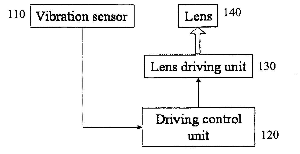
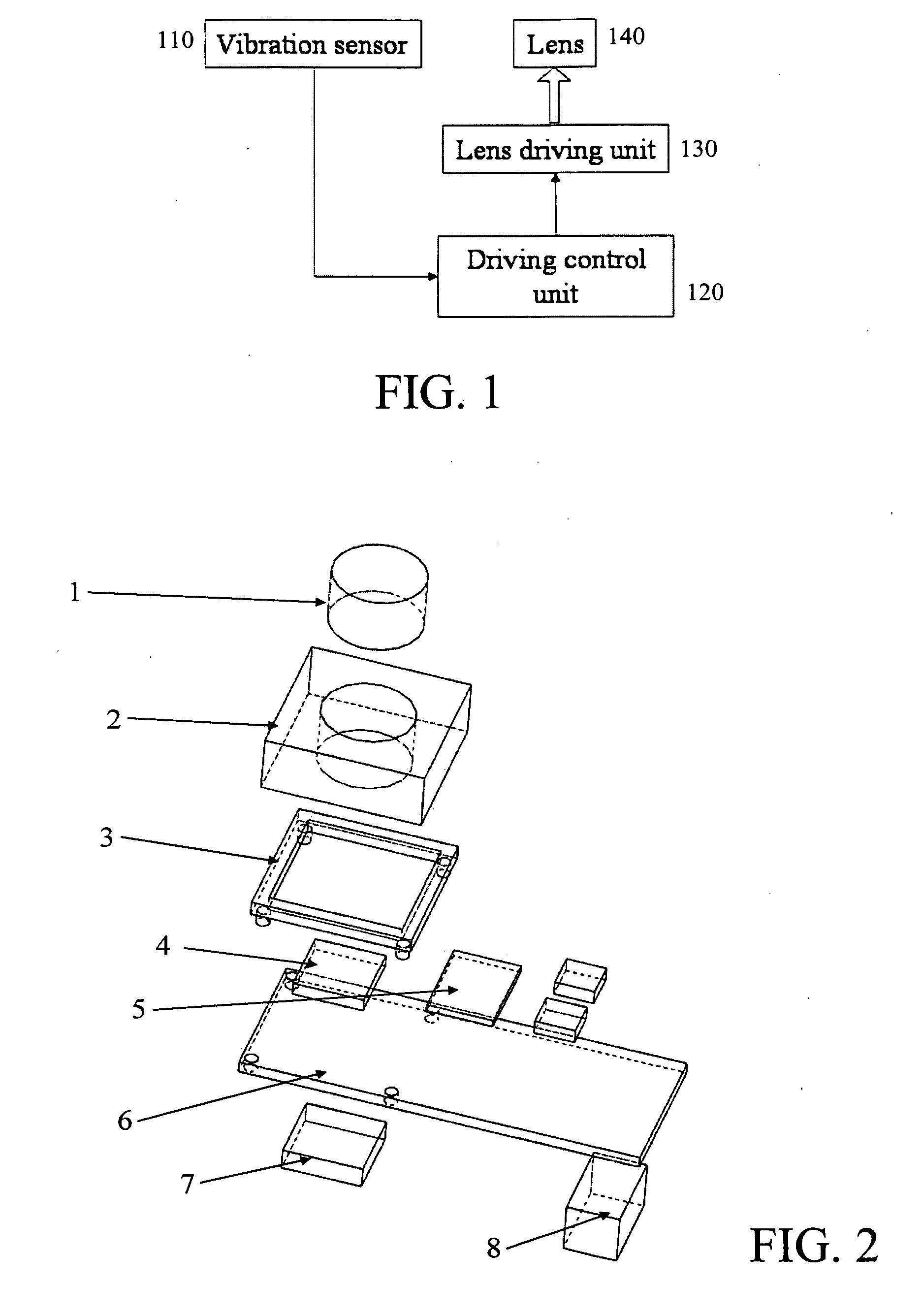
[0026]Referring to FIG. 1, in an embodiment of the present invention, an optical module includes a lens unit 140, a lens driving unit 130, a driving control unit 120, and a vibration sensing unit 110. The lens unit 140 is configured to collect optical signals of outside object. The lens driving unit 130 carries the lens unit 140, and is capable of driving the lens unit 140 to perform an up and down, left and right, or forward and backward linear movement or a rotation under the control of a control signal. The lens driving unit 130 can be a piezoelectric type actuator, an electro-active polymer type actuator, or a voice coil motor type actuator. The lens driving unit 130 can further comprise various combinations of piezoelectric actuator, electro-active polymer actuator, and voice coil motor actuator. The lens driving unit 130 drive the lens unit 140 to realize vibration...


PUM


Abstract

An optical module, a camera, and a mobile terminal device are provided. The optical module includes a lens unit, a lens driving unit, a driving control unit, and a vibration sensing unit. The vibration sensing unit is configured to detect vibration/shaking of the optical module, the camera, or the mobile terminal device and transmit a detected signal to the driving control unit. The driving control unit generates a corresponding vibration/shaking compensation signal according to the detected signal of the vibration sensor, and performs a vibration/shaking compensation movement by driving the lens with the lens driving unit. The optical module is applied in the camera and the mobile terminal device. The present invention has not only an auto-focusing function, but also an added anti-vibration function, so as to overcome influences on image degradation resulted from vibration/shaking of the optical module, the camera, or the mobile terminal device.

Description

BACKGROUND OF THE INVENTION[0001]1. Field of Invention[0002]The present invention relates to an optical system, and more particularly to an optical module, a camera, and a mobile terminal device applying the optical module.[0003]2. Related Art[0004]With the continuous development of digital technology, the performance of a camera is increasingly improved. In order to form a clear image of an object in a camera, a lens actuator in the camera is generally used to control a position of the lens or move the lens to achieve a good focusing. At present, the above process is usually automatically implemented by a control circuit. Thereby, such a function is called auto-focusing, the key point of which is to control the lens to move along a direction of an optical axis of the lens, so as to change a distance between the lens and a camera sensor.[0005]Popular digital cameras nowadays are usually very sophisticated, and can be used in various occasions. Generally, no corresponding fixing devi...

Claims


Application Information

Patent Timeline
IPC IPC(8): G02B27/64H04N5/228G03B5/00
CPCG03B5/00H04N5/2254G03B2205/0007H04N5/23258H04N5/2328H04N5/2257H04N23/60H04N23/57H04N23/55H04N23/6812H04N23/685
Inventor LAM, SIO KUANFAN, KIN MINGLIU, TIEGANGFAN, WING MING
Owner HONG KONG APPLIED SCI & TECH RES INST
Why Eureka
Try Eureka