

Catalyst System for CO-Removal
a catalyst system and co-removal technology, applied in the field of catalyst systems, can solve the problems of high degree of unwanted hsub>2/sub>-oxidation, inability to completely eliminate carbon monoxide, etc., to achieve convenient carbon monoxide oxidation, no comparison improvement, and low back pressure
- Summary
- Abstract
- Description
- Claims
- Application Information
AI Technical Summary
Benefits of technology
Problems solved by technology
Method used
Image

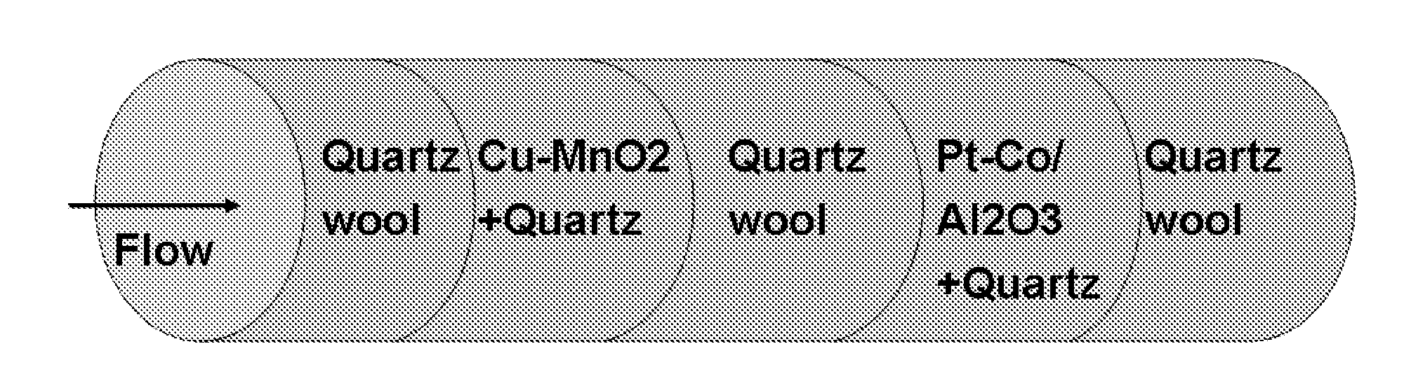
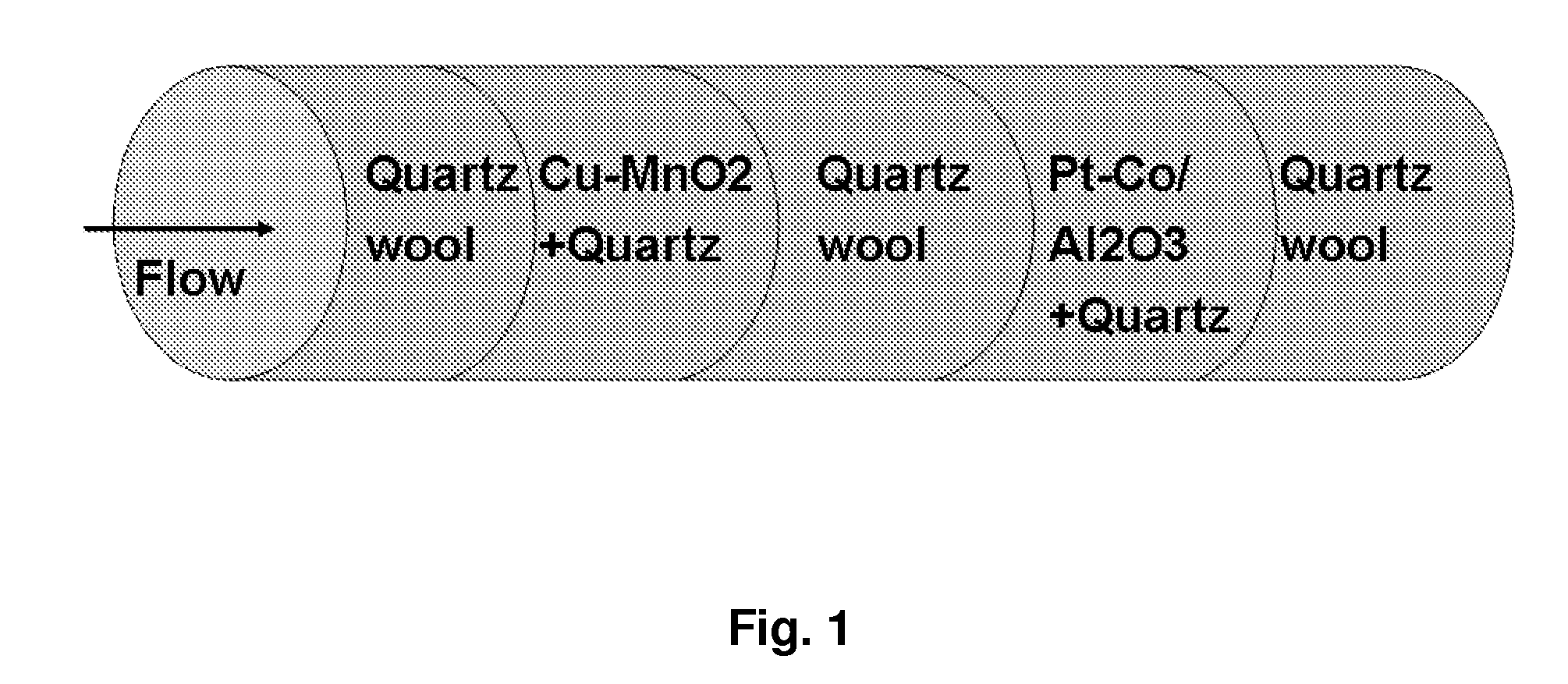
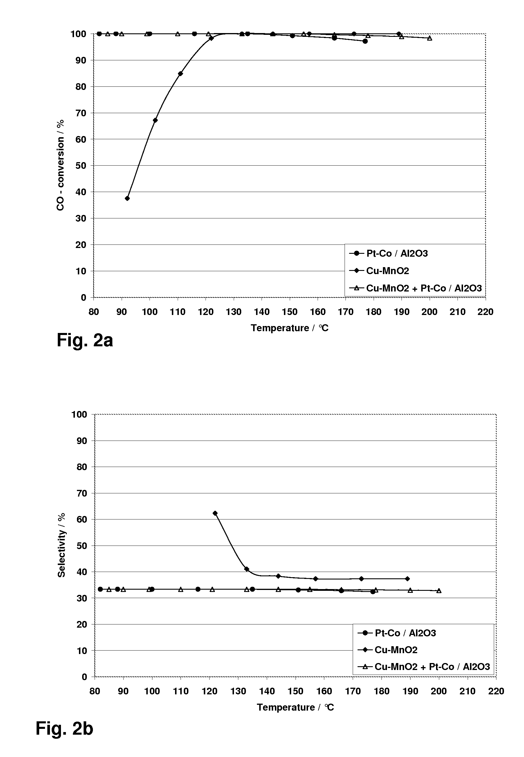
Examples
examples
Preparation of Pt—Co catalyst on alumina
[0040]The high-surface area alumina was supplied from Alfa Aesar. The surface area was 255 m2 / g after preliminary calcinations at T=750° C. The alumina support was then impregnated with a hot solution (85° C.) containing tetraamineplatinum (II) nitrate, cobalt nitrate and tartaric acid using so-called “wetness impregnation”. Tartaric acid was added in a slight excess (1.2 of stoichiometric molar ratio of tartatic acid / Pt+Co). Pt loading was selected as 5 wt %, and Co loading was 1.5 wt % accordingly. The samples were dried at 77° C. in drying box overnight and then were finally calcined at 550° C. for 2 hours in the air.
Cu—MnO2 catalyst preparation
[0041]The Preparation Procedure Contains Three Steps, Namely:[0042]1) Co-precipitation of copper and manganese mixed oxide from the mixture of manganese (II) nitrate and copper nitrate (2 / 1 molar ratio Mn / Cu) using excess of potassium carbonate as a precipitation agent at room temperature with the fo...
PUM
| Property | Measurement | Unit |
|---|---|---|
| Temperature | aaaaa | aaaaa |
| Temperature | aaaaa | aaaaa |
| Ratio | aaaaa | aaaaa |
Abstract
Description
Claims
Application Information