Rolled electrode battery and manufacturing method therefor

a technology of electrode batteries and rolling electrodes, which is applied in the direction of wound/folded electrode electrodes, sustainable manufacturing/processing, cell components, etc., can solve the problems of increased overall thickness of the electrode body, difficulty in applying a battery in which electric, and overheating/burning, etc., and achieves the effect of reducing size and increasing curren

Inactive Publication Date: 2009-09-24
KK TOSHIBA
View PDF2 Cites 86 Cited by
  • Summary
  • Abstract
  • Description
  • Claims
  • Application Information

AI Technical Summary

Benefits of technology

[0013]This invention has been made in consideration of these circumstances, and its object is to provide a rolled electrod

Problems solved by technology

However, it is difficult to apply a battery in which electric power is extracted from the electrode body through the tabs to an electric vehicle.
When a large current flows through a battery of this type, overheating/burning may be caused at junct

Method used


Image

  • Rolled electrode battery and manufacturing method therefor
  • Rolled electrode battery and manufacturing method therefor
  • Rolled electrode battery and manufacturing method therefor

Examples


first embodiment

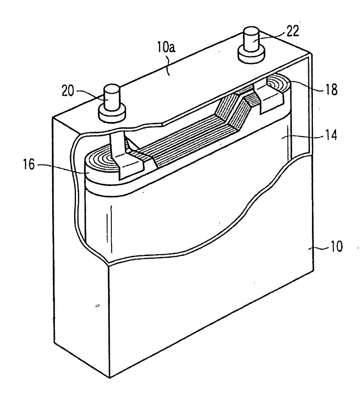
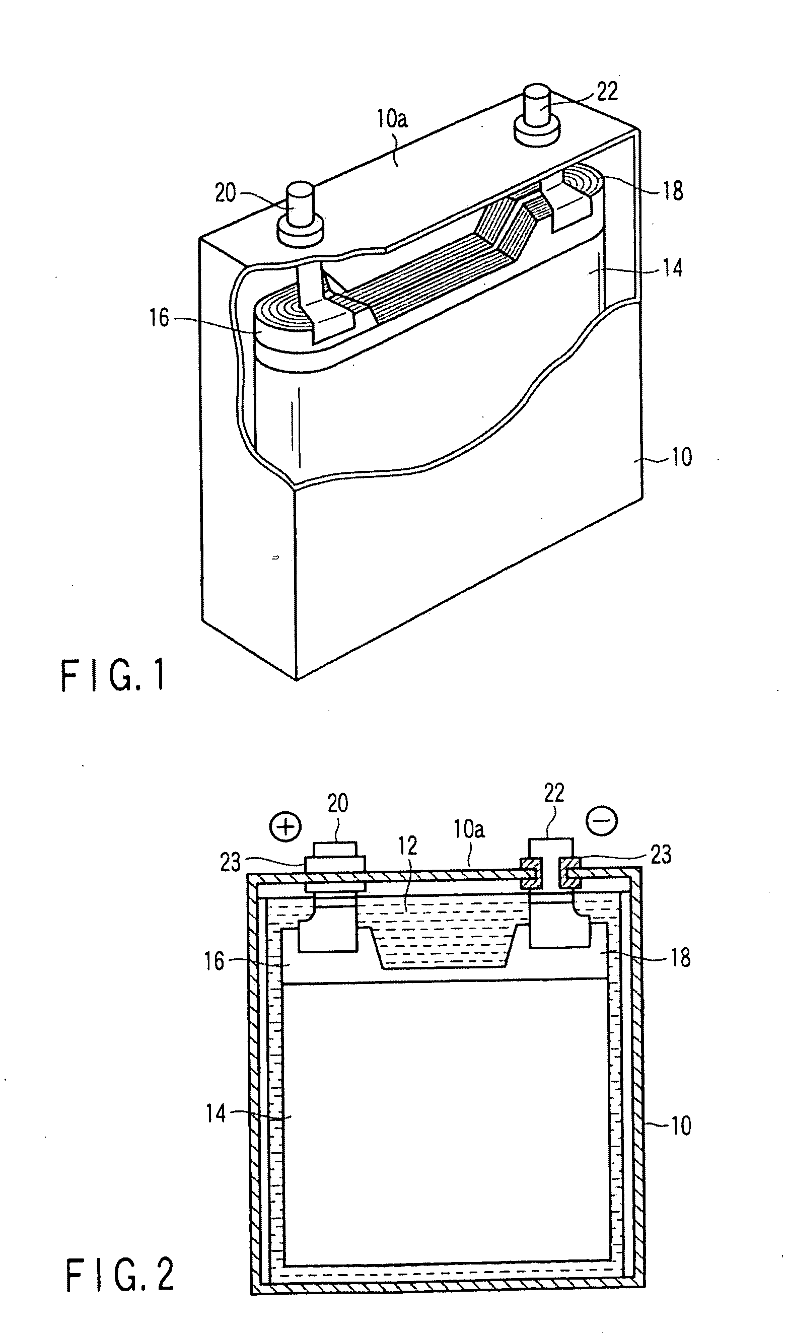
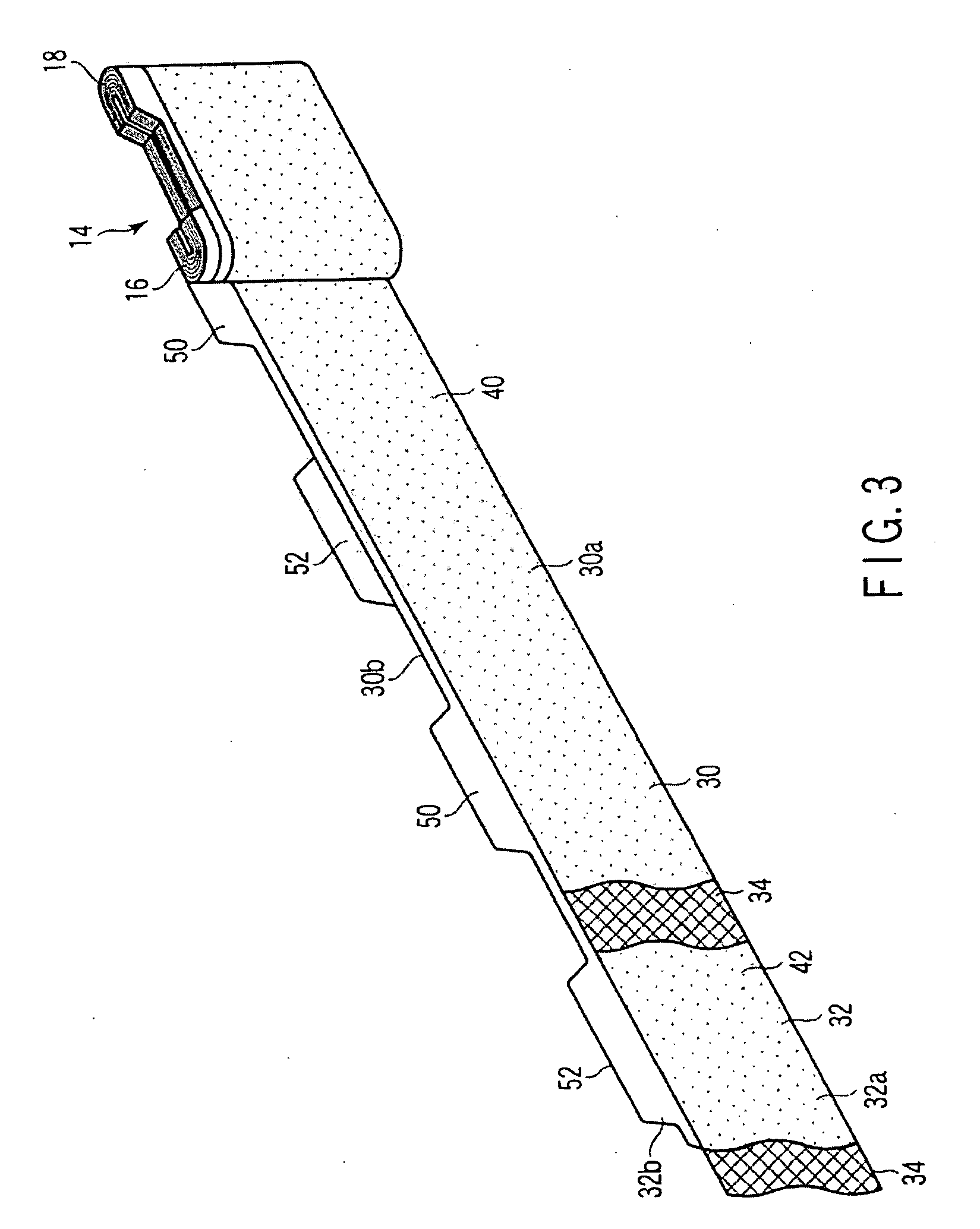
[0028]A rolled electrode battery according to this invention will now be described in detail with reference to the drawing. FIG. 1 is a cutaway perspective view of the rolled electrode battery, FIG. 2 is a longitudinal sectional view of the rolled electrode battery, and FIG. 3 shows a laminate structure of an electrode plate along with a partially developed electrode body.

[0029]As shown in FIGS. 1 and 2, the rolled electrode battery is provided with a case or can 10 in the form of a flat rectangular box and a rolled electrode body 14 in the form of a flat cube that is contained together with an electrolyte solution 12 in the case. The electrode body 14 integrally includes a positive electrode tab 16 and a negative electrode tab 18 that protrude in the same direction along its axis. A positive electrode terminal 20 having a shaft portion is joined to the positive electrode tab 16, while a negative electrode terminal 22 having a shaft portion is joined to the negative electrode tab 18...

second embodiment

[0062]With a rolled electrode battery lugs of an electrode body 14 are formed by means of a press. As shown in FIGS. 8 to 10, in this case, intervals C1 to Cn−1 between lugs 50 of a positive electrode plate 30 are adjusted to a constant value C, and intervals C1 to Cn−1 between lugs 52 of a negative electrode plate 32 are also adjusted to the constant value C. Further, a width b1 of the smallest-width lugs 50 and 52 that are situated at one ends of the positive electrode plate 30 and the negative electrode plate 32 is adjusted to (W−D−x), and a width bn of the largest-width lugs 50 and 52n that are situated at the other ends of the positive electrode plate and the negative electrode plate is adjusted to (bn+2b1+πD).

[0063]A positive electrode tab 16 and a negative electrode tab 18 are formed based on the lugs 50 and 52 by rolling the positive electrode plate 30 and the negative electrode plate 32 described above to form the electrode body 14. These positive and negative electrode ta...


PUM

PropertyMeasurementUnit
Lengthaaaaaaaaaa

Abstract

A rolled electrode battery includes a rolled electrode body including band-shaped positive and negative electrode plates formed individually with electrode active material layers, which are rolled with a band-shaped separator interposed between them and formed into a flat shape. Each of the electrode plates includes a band-shaped electrode portion formed with the electrode active material layer and contacting the separator and a side edge portion projecting from the separator and not formed with an electrode active material layer. The side edge portion forms lugs arranged at intervals along the lengths of the electrode plates. The positive and negative electrode plates are rolled in layers so that the lugs of the positive electrode plate are laminated to one another to form a positive electrode tab and that the lugs of the negative electrode plate are laminated to one another to form a negative electrode tab.

Description

CROSS REFERENCE TO RELATED APPLICATIONS[0001]This is a Continuation Application of PCT Application No. PCT / JP2008 / 054202, filed Mar. 7, 2008, which was published under PCT Article 21(2) in Japanese.[0002]This application is based upon and claims the benefit of priority from prior Japanese Patent Application No. 2007-062589, filed Mar. 12, 2007, the entire contents of which are incorporated herein by reference.BACKGROUND OF THE INVENTION[0003]1. Field of the Invention[0004]The present invention relates to a rolled electrode battery, including an electrode body formed by rolling band-shaped positive and negative electrode plates into a flat shape with a separator therebetween, and a method of manufacturing the rolled electrode battery.[0005]2. Description of the Related Art[0006]With the recent increase of interest in environmental problems, the development of electric vehicles and hybrid electric vehicles has been advanced and attracting public attention. Batteries used in these elec...

Claims


Application Information

Patent Timeline
IPC IPC(8): H01M6/10H01M6/00H01M10/04H01M10/0525H01M10/0587H01M50/536H01M50/538
CPCH01M2/1673H01M2/263H01M4/13Y10T29/49112H01M10/0431H01M10/0587Y02E60/122H01M4/139Y02E60/10H01M50/46H01M50/538Y02P70/50H01M50/536
Inventor KOSUGI, SHINICHIRO
Owner KK TOSHIBA
Why Eureka
Try Eureka