Polishing Apparatus and Polishing Method

a polishing apparatus and polishing technology, applied in the direction of gear teeth, gear teeth, gear machine, etc., can solve the problems of degrading the flatness around the edge of the object under polishing, inability to extend a flat region to the vicinity of the edge, and inability to sufficiently support the exclusion of the set edg

Active Publication Date: 2009-09-24
EBARA CORP
View PDF7 Cites 20 Cited by
  • Summary
  • Abstract
  • Description
  • Claims
  • Application Information

AI Technical Summary

Benefits of technology

[0026]In view of the foregoing findings, and to achieve the above objects, the invention described in claim 1 provides a polishing apparatus including a polishing section having a polishing member and a holding member, for applying a pressure be

Problems solved by technology

This extending polishing member causes an excessive polishing pressure to be applied around the edge of the object under polish, resulting in a degraded flatness around the edge of the object under polish.
Therefore, one challenge imposed to the polishing apparatuses is to extend a region of high flatness closest possible to the edge, such that the polishing apparatuses can sufficiently support edge exclusion defined by semiconductor device manufacturers and the like.
However, in such a pol

Method used


Image

  • Polishing Apparatus and Polishing Method
  • Polishing Apparatus and Polishing Method
  • Polishing Apparatus and Polishing Method

Examples


first embodiment

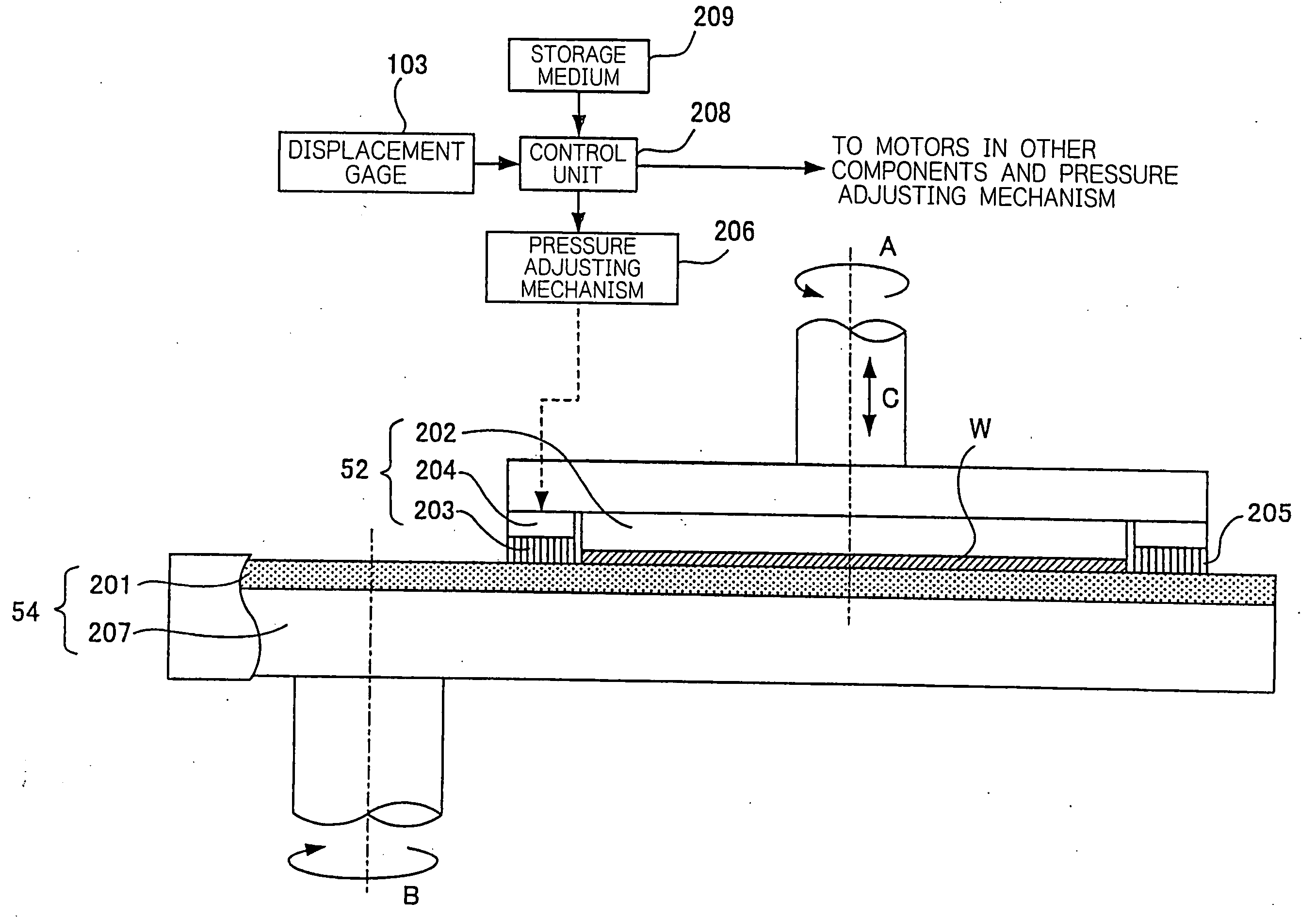
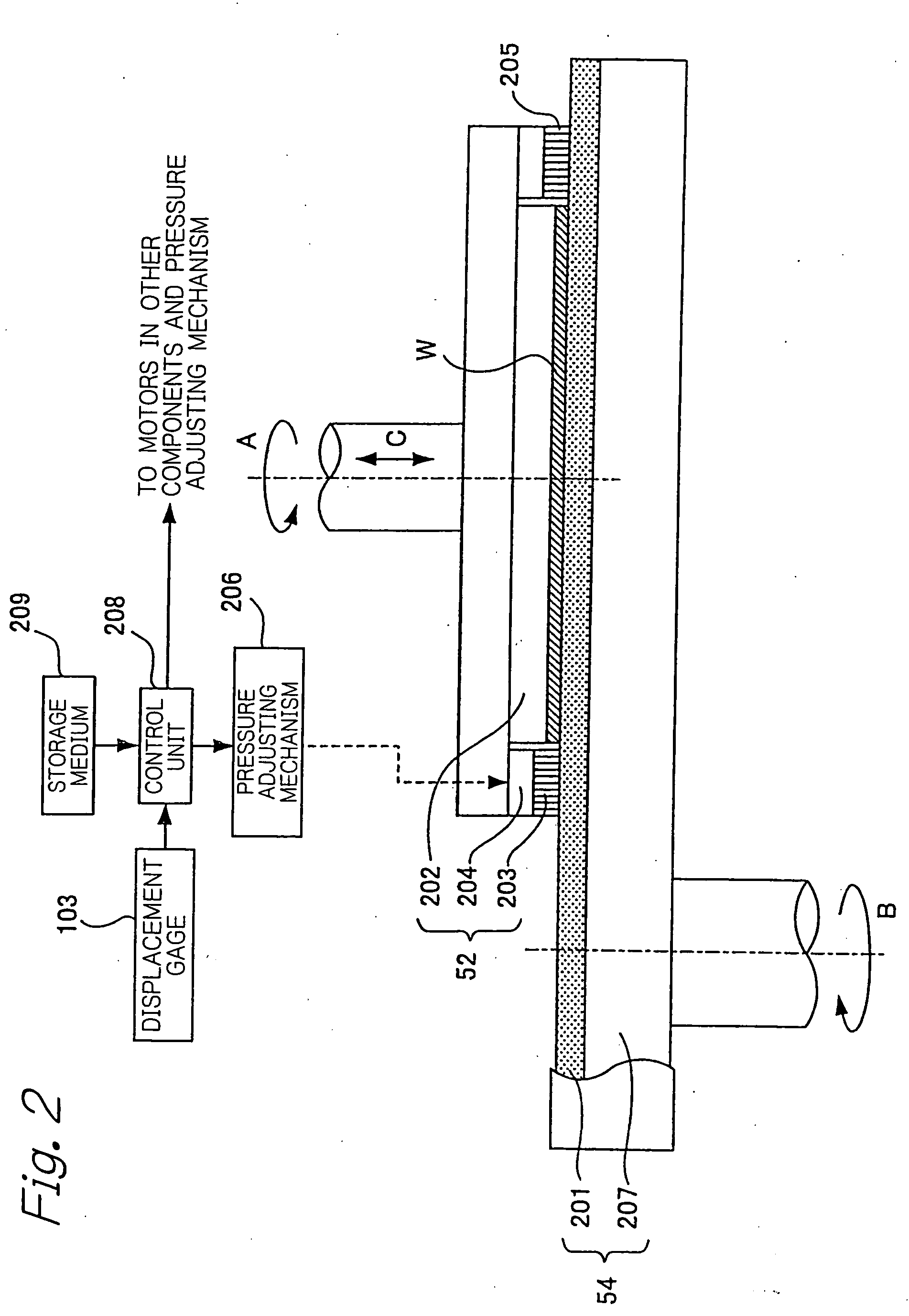
[0148]FIG. 2 is a diagram illustrating the polishing section and associated control system in the polishing apparatus according to the present invention, wherein the polishing section comprises a top ring and a polishing table. FIG. 2 schematically illustrates a cross-sectional view of part of the top ring 52 and polishing table 54, and an example of the control system. The top ring 53 and polishing table 55 also have similar structures. As illustrated in FIG. 2, the top ring 52 is positioned such that a wafer W does not extend off the edge of a polishing pad 201. The top ring 52 for holding a wafer W, which is an object under polish, comprises an air bag 202 for pressing the wafer W against the polishing pad 201 with a predetermined pressure; a retainer ring 203 disposed to surround the wafer W; and an air bag 204 for pressing the polishing pad 201 around the wafer W against the retainer ring 203 with a predetermined supporting pressure. In the following description, a pressure wit...

second embodiment

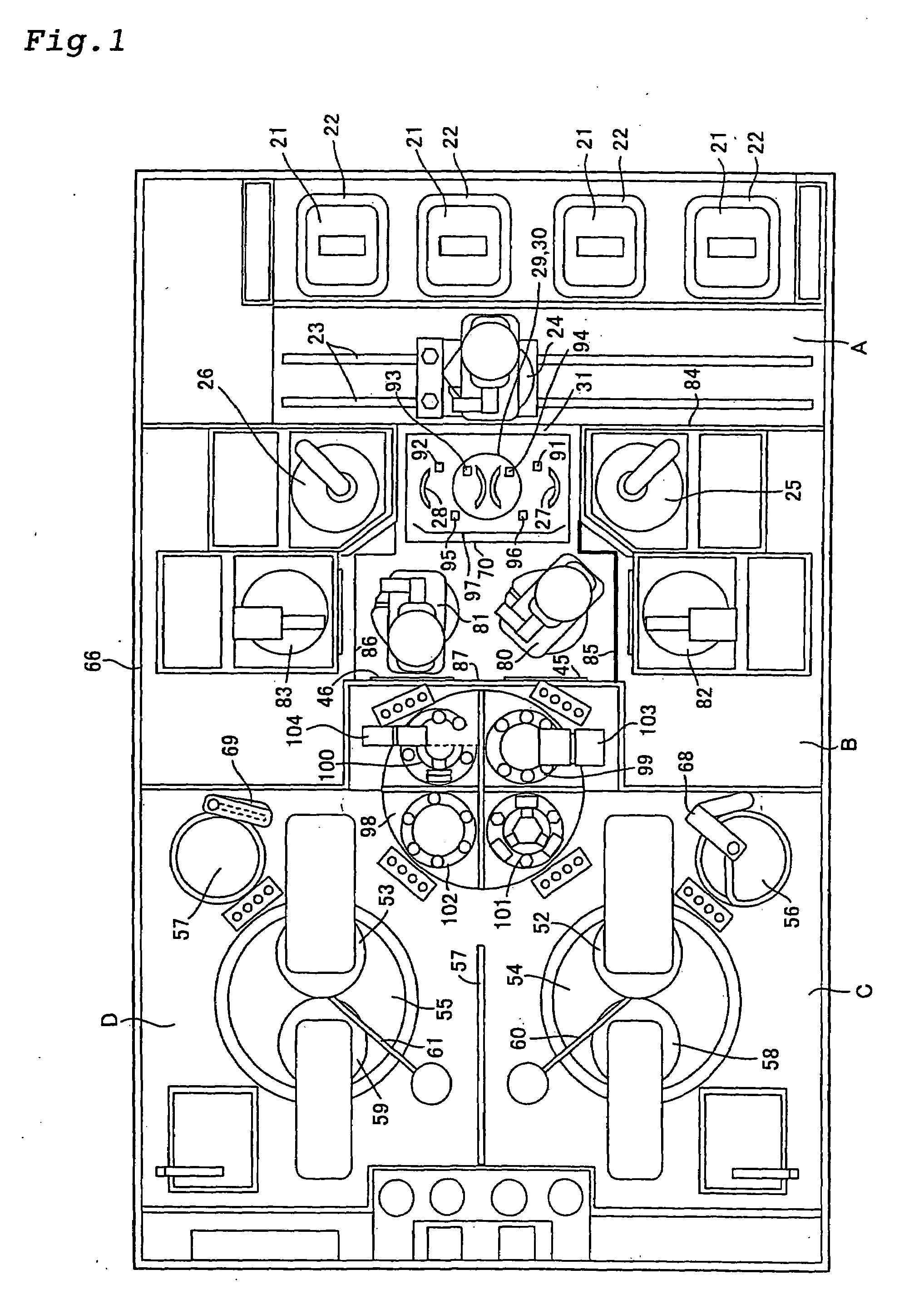
[0164]First, the second embodiment employs a retainer ring 301 made up of a plurality of pressing members having a pressing surface for pressing a polishing pad 201, instead of the single retainer ring 203 in FIG. 2. Specifically, the retainer ring 301 is made up of a predetermined number of independent pressing members which are sequentially arranged along the periphery of a wafer W and separated from each other by a predetermined angle along a plane which is passed by the center axis of the top ring 52′. In FIG. 5, the retainer ring 301 is made up of 12 independent pressing members 301a-301l which are sequentially arranged along the periphery of the wafer W, and separated from each other by 30° along the plane which is passed by the center axis of the top ring 52′. As illustrated in FIGS. 4 and 5, the pressing member 301a comprises a single member 302 having an arc shape in the lengthwise direction and a rectangular cross-section, which is formed such that its inner peripheral sur...

third embodiment

[0170]FIG. 6 is a diagram schematically illustrating a polishing section in cross-section and a control system in the polishing apparatus according to the present invention, and FIG. 7 is a cross-sectional view when viewed in a direction of allows J, K along a line JK in FIG. 6. Components identical or corresponding to the components in FIGS. 2 and 4 are designated the same reference numerals, and repetitive description thereon is omitted.

[0171]In the third embodiment, the polishing section comprises a wafer holding unit and a wafer polishing unit. As a wafer holding unit for appropriately holding a wafer W, a vacuum chuck 401 is provided, as illustrated in FIG. 6. The vacuum chuck 401, which is made in a discoidal shape, can vacuum-absorb the wafer W with a mechanism (not shown) capable of vacuum absorption to hold the wafer W on its top surface, with a surface to be polished of the wafer W being oriented upward. One end of a shaft 402 is secured to the bottom surface of the vacuum...


PUM

PropertyMeasurementUnit
Thicknessaaaaaaaaaa
Pressureaaaaaaaaaa
Heightaaaaaaaaaa

Abstract

A polishing apparatus is provided for polishing wafers at a high yield rate even if roll-off exists. The polishing apparatus polishes a wafer W by applying a pressure between a polishing member (polishing pad) 201 and the wafer W held by a holding member (top ring) 52 and relatively moving the polishing member 201 to the wafer W. The polishing apparatus comprises a top ring 52 for holding the wafer W, a pressure adjusting mechanism 206 for adjusting a supporting pressure with which the wafer W is supported on a supporting surface by a retainer ring 203, and a control unit 208 for controlling the pressure adjusting mechanism 206 to bring the supporting pressure to a desired pressure based on a roll off quantity of the wafer W. The top ring 52 comprises an air bag 202 for pressing the wafer W against the polishing pad 201, a retainer ring 203 which surrounds the wafer W, and an air bag 204 for pressing the retainer ring 203.

Description

TECHNICAL FIELD[0001]The present invention relates to a polishing apparatus and a polishing method for polishing optical parts, mechanical parts, ceramics, metals, and the like, and more particularly, to a polishing apparatus and a polishing method suitable for polishing an object under polish such as a wafer formed with semiconductor devices into a flat and mirror-surface state.BACKGROUND ART[0002]In recent years, as semiconductor devices are increasingly more integrated, circuit wires are made thinner, and the dimensions of integrated semiconductor devices are made smaller and smaller. This leads to the need for a process of removing a coating formed on the surface of a wafer to planarize the surface, and as an approach of this planarizing method, the wafer is polished by a chemical mechanical polishing (CMP) apparatus. The chemical mechanical polishing apparatus comprises a polishing member such as polishing cloth, pad and the like; and a holding member such as a top ring, a chuc...

Claims


Application Information

Patent Timeline
IPC IPC(8): B24B49/00B24B1/00B24B49/08B24B49/16B24D11/00B24B37/04
CPCB24B37/005B24B37/04B24B37/10H01L21/304
Inventor FUKUDA, AKIRAMOCHIZUKI, YOSHIHIROHIROKAWA, KAZUTO
Owner EBARA CORP
Why Eureka
Try Eureka