
Surgical Articles and Methods for Treating Pelvic Conditions

a technology of pelvis and surgical articles, applied in the field of pelvis surgical articles and methods, can solve the problems of long surgical procedure time, weakening or damage to the normal pelvis support system, and distension of the vaginal apex outside of the vagina, and achieve the effect of reducing the for

Active Publication Date: 2009-09-24
BOSTON SCI SCIMED INC
View PDF103 Cites 45 Cited by
  • Summary
  • Abstract
  • Description
  • Claims
  • Application Information

AI Technical Summary

Benefits of technology

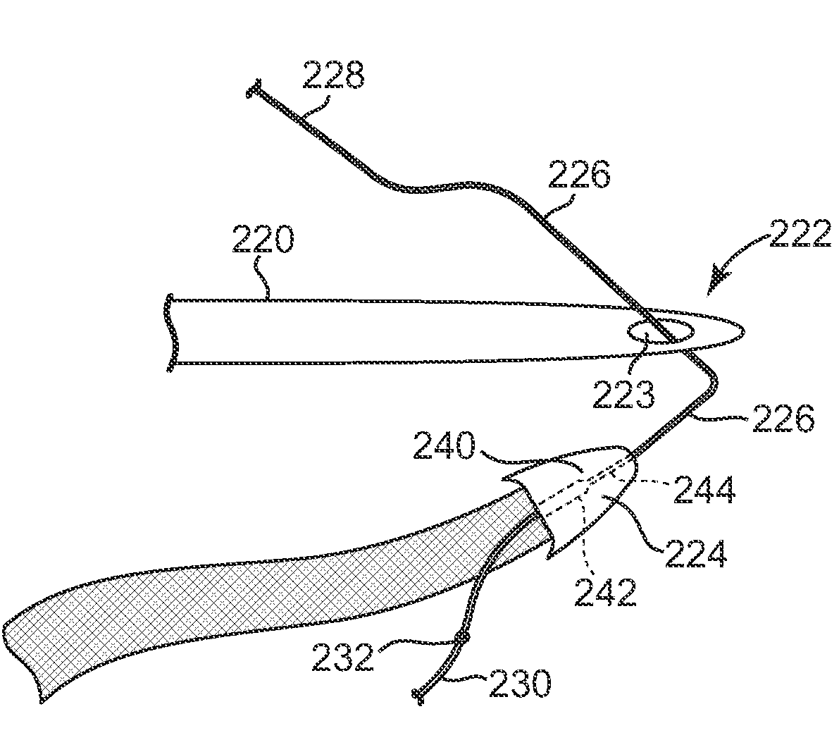
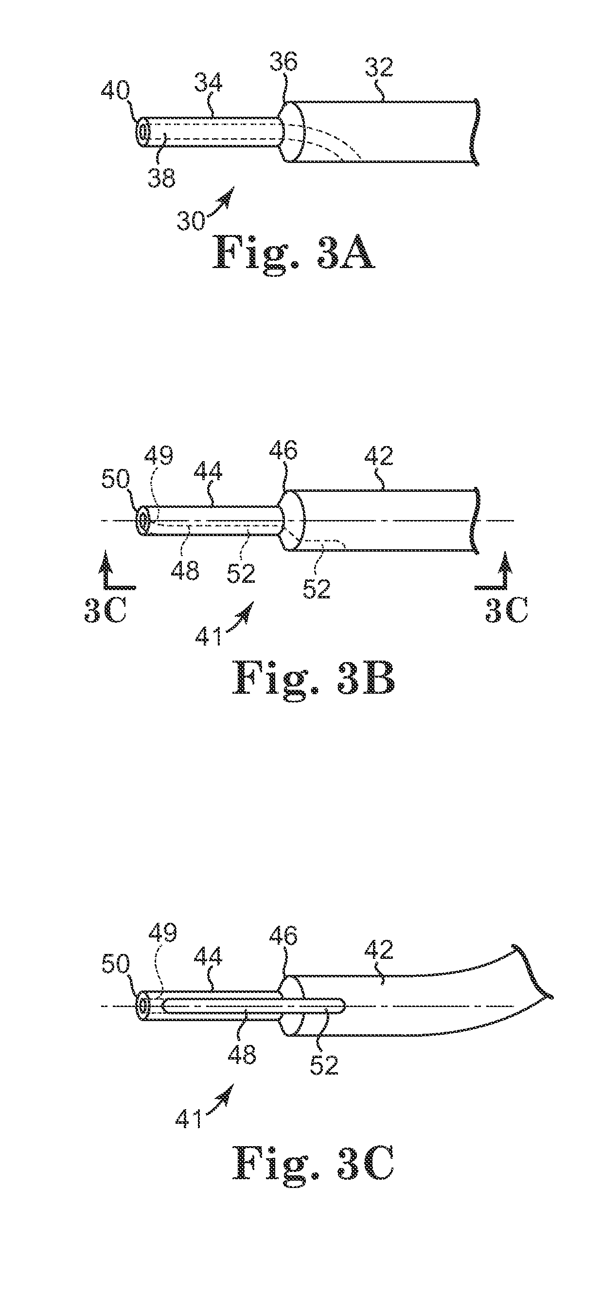
[0011]An implant can be implanted at the pelvic region by use of an insertion tool. Embodiments of insertion tools for use as described herein can include a needle tip that includes an aperture that allows for passage of guide. The aperture allows a user to use the guide to move the needle tip into engagement with a self-fixating tip (which is also engaged with the same guide), after the self-fixating tip has been placed at tissue of a patient's pelvic region. The aperture can also preferably allow the needle tip to engage the self-fixating tip while the needle tip is in engagement with the guide. This allows the needle tip to engage the self-fixating tip, located at tissue of a patient's pelvic region, and allow the self-fixating tip to be adjusted after initial placement at tissue of a pelvic region.
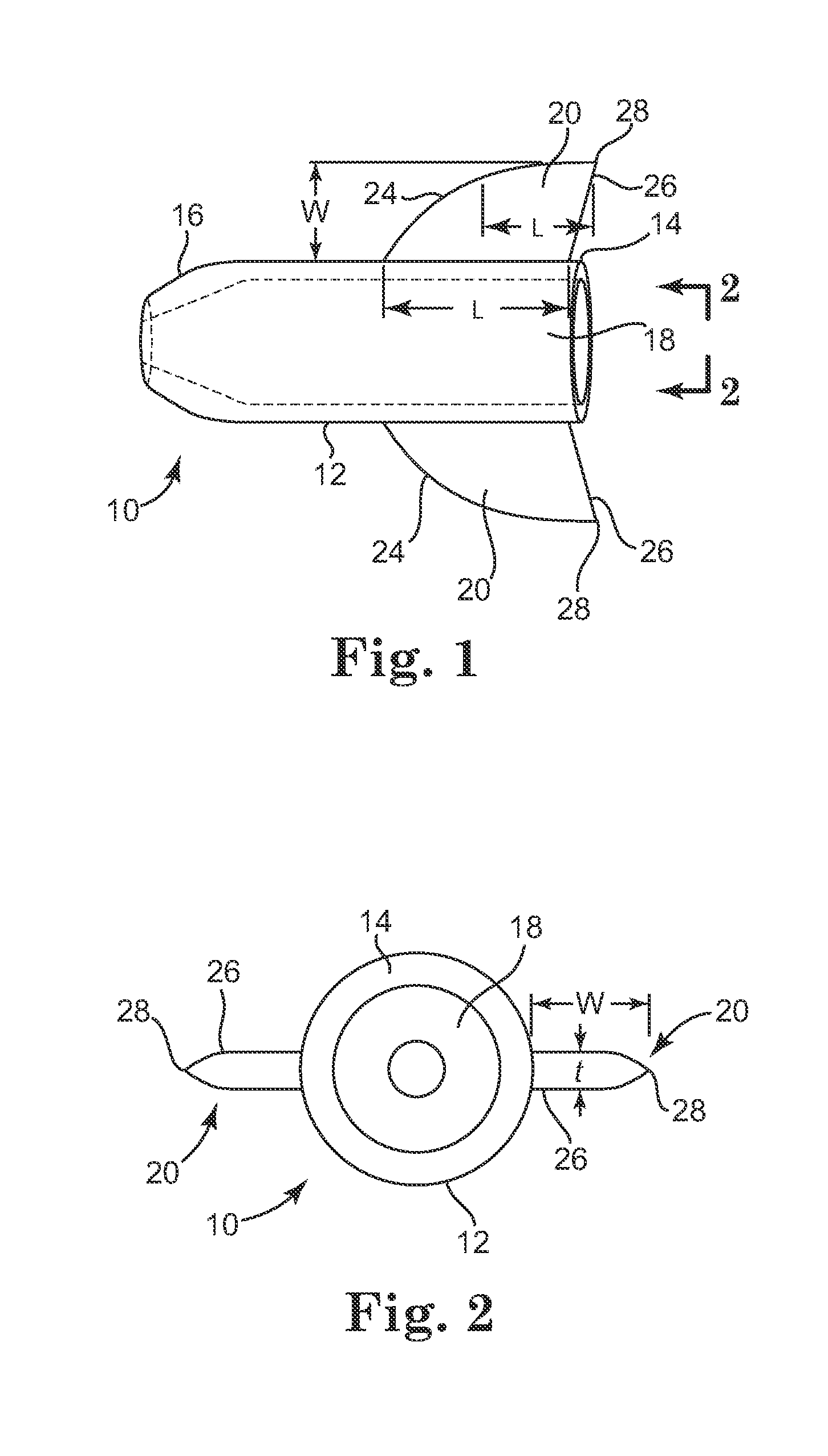
[0012]Alternately or in addition to an aperture at a needle tip, certain embodiments of needle tips for use according to the present description can include one or more extension guard at the distal end of the needle at a location where the distal end meets a self-fixating tip. An extension guard is a portion of an insertion tool that extends laterally from a needle and is shaped to correspond to a shape or form of a trailing (proximal) portion of a self-fixating tip when the self-fixating tip is engaged with the needle tip. The extension guard provides streamlining behind (proximal to) a trailing surface of a self-fixating tip, such as behind a base or a lateral extension of a self-fixating tip. The streamlining can reduce the force required to remove a self-fixating tip from tissue or to adjust the location of the self-fixating tip in a direction opposite of the direction of insertion. The combined form of a needle extension guard situated proximal to a trailing surface of a lateral extension or other trailing surface of a self-fixating tip includes a smooth, e.g., streamlined, form from a proximal end to a distal end.
[0019]In another aspect, the invention relates to a combination that includes a pelvic implant and insertion tool. The implant includes a support portion, an extension portion, and a self-fixating tip connected to the extension portion. The self-fixating tip includes a base that has a proximal base end and a distal base end, the proximal base end being connected to the extension portion; and a lateral extension extending from the base. The insertion tool includes a handle and a needle extending from the handle. The needle includes: a proximal end attached to the handle and a distal end that includes a needle tip configured to engage the self-fixating tip. The insertion tool includes an extension guard that, when the needle tip engages the self-fixating tip to allow the needle to push the self-fixating tip for surgical installation, the extension guard is located proximal to the lateral extension and reduces the force required to move the self-fixating tip in a proximal direction through muscle tissue.

Problems solved by technology

Pelvic disorders such as these can result from weakness or damage to normal pelvic support systems.
In its severest forms, vaginal vault prolapse can result in the distension of the vaginal apex outside of the vagina.
These procedures often involve lengthy surgical procedure times.
For various reasons, the levator may suffer weakness or injury such as damage to the levator hiatus, ballooning or levator avulsion, any of which that can result in symptoms such as prolapse, fecal incontinence, and other conditions of the pelvis.
Another levator defect is levator ballooning, which refers to distension of levator muscles.
A different levator defect is a defect of the levator hiatus, which can reduce the stability of the pelvic floor and may result in sexual dysfunction, defecatory dysfunction, rectal prolapse, and fecal incontinence.

Method used


Image

  • Surgical Articles and Methods for Treating Pelvic Conditions
  • Surgical Articles and Methods for Treating Pelvic Conditions
  • Surgical Articles and Methods for Treating Pelvic Conditions

Examples


Embodiment Construction

[0040]The invention relates to surgical instruments, assemblies, combinations (e.g., of implants and tools), and implantable articles for treating pelvic floor disorders such as prolapse (e.g., vaginal prolapse), incontinence (urinary and fecal incontinence), conditions of the pelvic floor such as the perineal body, conditions of levator muscle (such as a component of levator muscle), conditions of the levator hiatus, and combinations of two or more of these. According to various embodiments, a surgical implant can be used to treat a pelvic condition, wherein the method includes placing an implant in a manner to support tissue of the pelvic region in a male or female. Methods involve the use of an implant and insertion tool, the implant including at least one self-fixating tip that becomes implanted into tissue of the pelvic region.

[0041]Certain embodiments of implants and tools can be designed and used according to the current description in a manner that allows for placement and a...


PUM


Abstract

An implant, insertion tool, combinations, and associated methods, that involve placement of a self-fixating tip at tissue of the pelvic region, wherein an insertion tool includes one or more of an aperture for engaging a guide and an extension guard, the method optionally allowing for initial placement of a self-fixating tip at tissue of the pelvic region and adjustment of the location of the self-fixating tip. A threading guide is provided to assist in threading the guide through the aperture. An anchor also provided to with a retaining member to retain the anchor in tissue.

Description

PRIORITY[0001]This non-provisional application claims the benefit of U.S. Provisional Application Ser. No. 61 / 054,015 filed on May 16, 2008, by Jason W. Ogdahl entitled “Threading Guide for Re-Docking Suture On MiniArc I”; U.S. Provisional Application Ser. No. 61 / 055,054, filed on May 21, 2008, by Brent A. Binkowski entitled “Scaffold-Tine Anchoring System”; and is a Continuation-In-Part of U.S. National Stage application Ser. No. 12 / 446,492, filed on Oct. 26, 2007, by John F. Otte, et al., entitled “Surgical Articles and Methods for Treating Pelvic Conditions.”FIELD OF THE INVENTION[0002]The invention relates to apparatus and methods for treating pelvic conditions by use of a pelvic implant to support pelvic tissue. The pelvic conditions include conditions of the female or male anatomy, and specifically include treatments of female or male urinary and fecal incontinence, treatment of female vaginal prolapse conditions including enterocele, rectocele, cystocele, vault prolapse, trea...

Claims


Application Information

Patent Timeline
IPC IPC(8): A61F2/02A61B17/00
CPCA61B17/0401A61B17/0485A61B2017/00805A61B2017/0409A61F2/0045A61B2017/044A61B2017/0445A61B2017/0458A61B2017/22038A61B2017/0412A61F2220/0016A61B17/3403A61B17/3468A61F2/0063A61F2002/0072
Inventor OGDAHL, JASON W.BINKOWSKI, BRENT A.JIMENEZ, JOSE' W.KHAMIS, CHAOUKI A.ROLL, JESSICA L.SOLARI, MICHELLE L.OTTE, JOHN F.DAHDAH, MONA N.
Owner BOSTON SCI SCIMED INC
Learn More