
Microstructural optimization of automotive structures

a microstructure optimization and automotive technology, applied in the field of microstructure optimization of automotive structures, can solve the problems of not being able to use the currently known hot stamping process, and achieve the effect of high strength

Inactive Publication Date: 2009-10-01
HONDA MOTOR CO LTD
View PDF18 Cites 36 Cited by
  • Summary
  • Abstract
  • Description
  • Claims
  • Application Information

AI Technical Summary

Benefits of technology

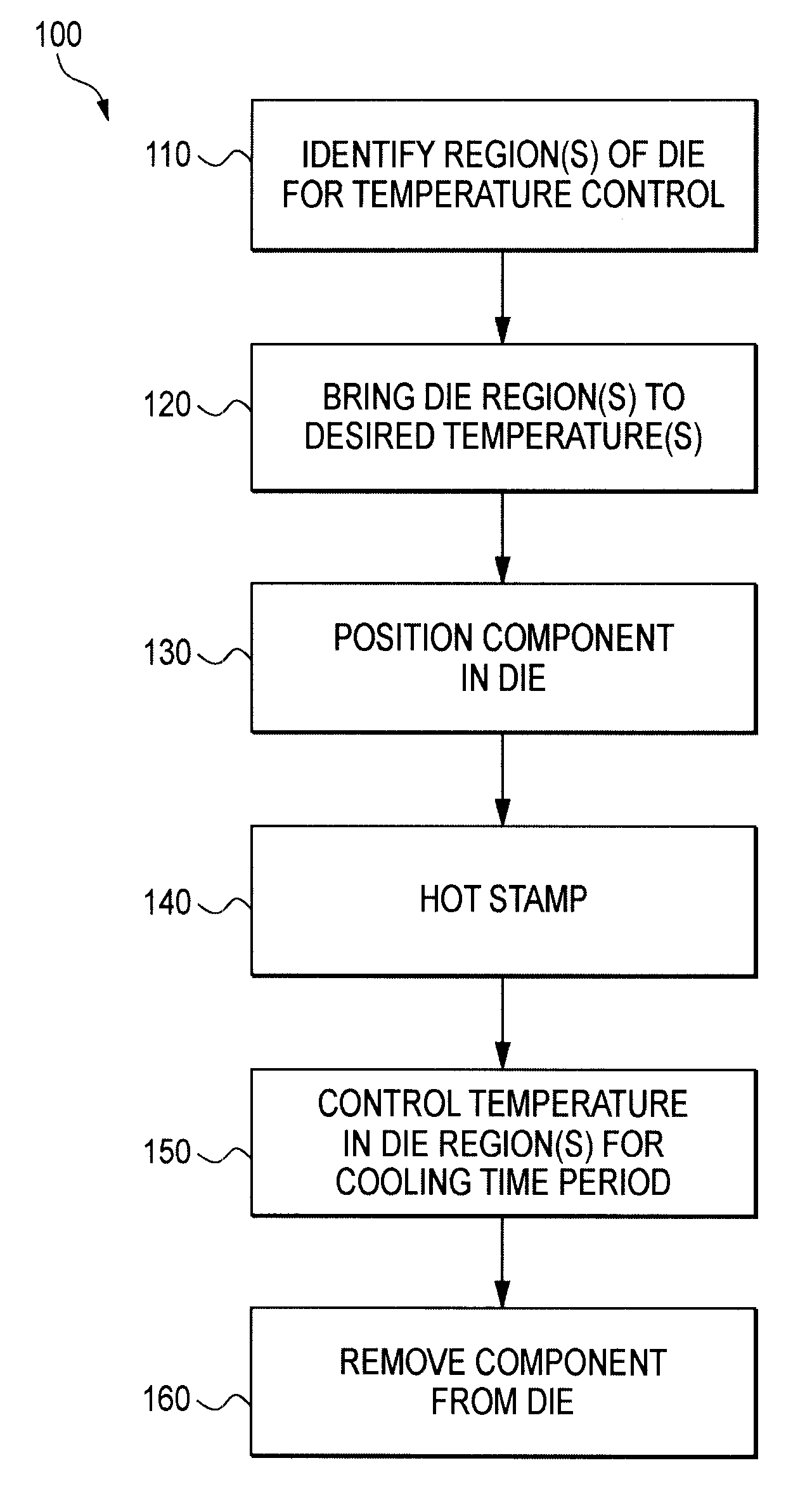
[0010]The difficulties and drawbacks associated with previous systems and methods are overcome in the present methods and apparatus for forming steel components having regions with particular physical properties different than the remainder of the component.

Problems solved by technology

Although satisfactory in many regards, these prior strategies for forming vehicle components utilize multiple operations which typically require additional manufacturing time, floor space, and capital expenditures.
And so, if it were desired to produce an engineered steel component with different physical characteristics at different regions of the component, it was generally not feasible to use currently known hot stamping processes.

Method used


Image

  • Microstructural optimization of automotive structures
  • Microstructural optimization of automotive structures
  • Microstructural optimization of automotive structures

Examples


Embodiment Construction

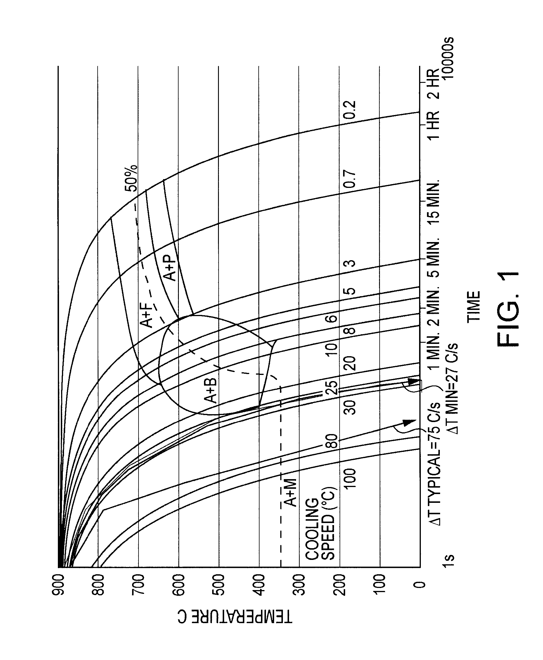
[0022]If a sample of steel is heated in a furnace, at a high enough temperature, it will enter an austenite (A) phase, as depicted on its corresponding phase diagram. In the austenite phase, the iron atoms in the steel are arranged in a face centered cubic (FCC) structure.

[0023]When cooled from this phase, the steel will enter a phase where both ferrite (F) and austenite co-exist. The ferrite phase is a body centered cubic (BCC) structure and cannot dissolve as much of the interstitial carbon as the austenite phase. Therefore, carbon in the regions that are transforming to ferrite must diffuse to the still existing austenite regions, thereby enriching these regions. A phase diagram allows the prediction of how much ferrite and austenite exist, as well as the carbon composition of each, when the phases are in equilibrium at any temperature and composition.

[0024]For most steels, below 727° C., the remaining austenite phase (which is of the eutectoid composition, 0.77 weight percent (w...


PUM

PropertyMeasurementUnit
temperatureaaaaaaaaaa

Abstract

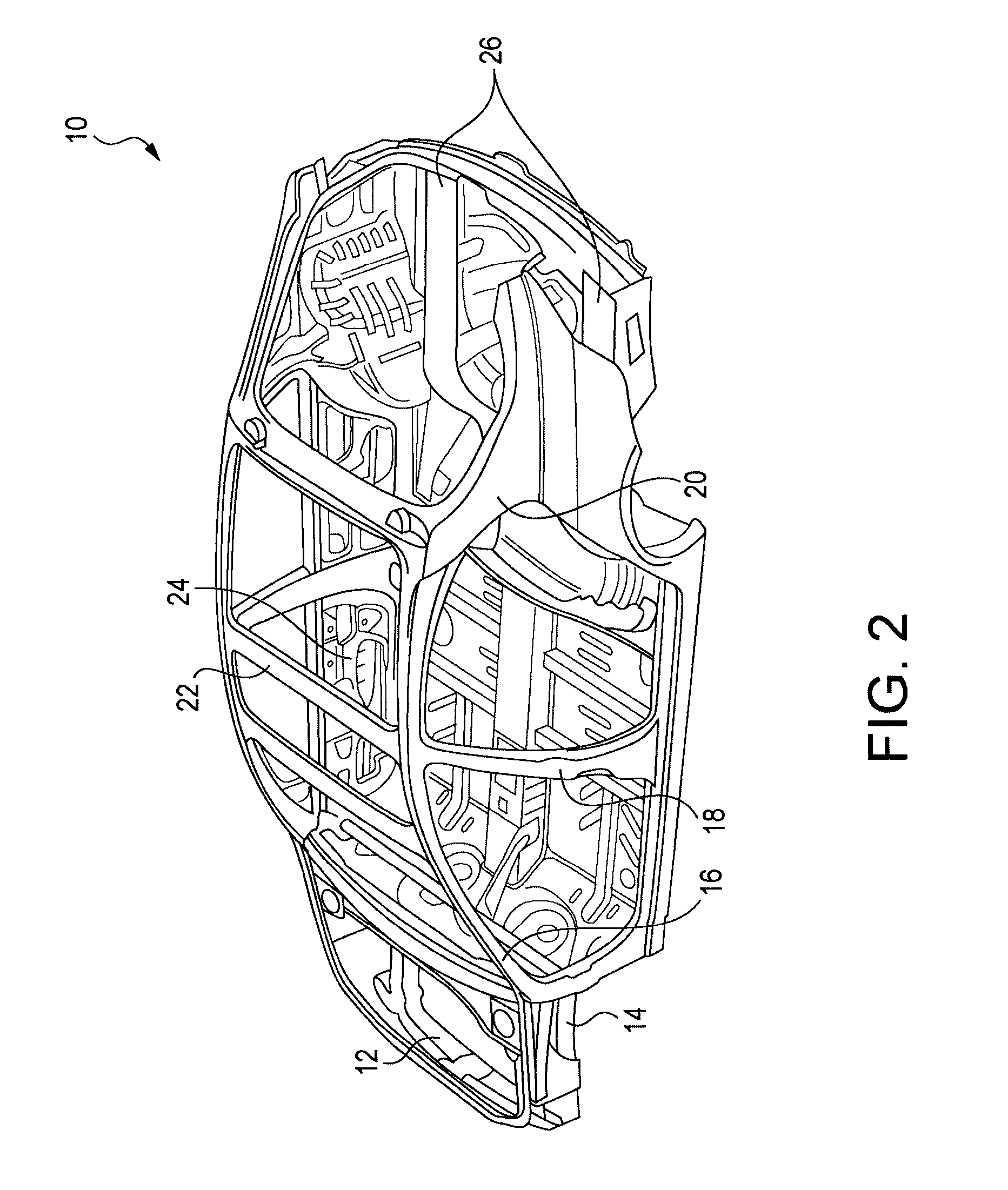
A process for hot stamping a steel component is described. The hot stamping process enables the formation of one or more regions of the component to exhibit specific physical properties different than other regions of the component. The various processes are particularly well suited for forming a variety of automobile structural members.

Description

CROSS REFERENCE TO RELATED APPLICATIONS[0001]This application claims priority upon U.S. provisional application Ser. No. 61 / 040,989 filed Mar. 31, 2008.BACKGROUND OF THE INVENTION[0002]The presently disclosed embodiments are directed to the field of automotive components, and particularly, controlling the microstructure of regions within such components by use of particular hot stamping processes.[0003]It is well known in the art to selectively heat treat vehicle components to impart desired characteristics to certain portions or regions of the component. For example, it is known to selectively heat a side intrusion door beam. Select portions of the beam may be heat treated to modify the load characteristics of the beam.[0004]It is also known to selectively cool or quench in order to harden regions of vehicle components such as bumpers. Such components can be formed to exhibit improved strength from selective austenitic-martensitic hardening. Bumpers can be formed by stamping a bump...

Claims


Application Information

Patent Timeline
Patent Type & Authority Applications(United States)
IPC IPC(8): C21D8/00
CPCC21D1/673C21D7/13C21D8/0205C21D8/04C22C38/28C21D2211/008C22C38/02C22C38/04C21D9/46
Inventor THOMAS, DYLANDETWILER, DUANE TRENT
Owner HONDA MOTOR CO LTD
Learn More