Oil seal and power transmission apparatus

a technology of oil seal and power transmission device, which is applied in mechanical equipment, engine components, gearing details, etc., can solve the problems of insufficient cooling the inability to direct the oil to the seal part of the oil seal,

Inactive Publication Date: 2009-10-01
AISIN AW CO LTD +1
View PDF11 Cites 4 Cited by
  • Summary
  • Abstract
  • Description
  • Claims
  • Application Information

AI Technical Summary

Benefits of technology

[0007]In the oil seal according to the first exemplary embodiment, the rotary shaft is sealed rotatably by the seal portion in an axially offset position from the fixed portion attached fixedly to the case of the power transmission apparatus. Thus, the oil that flies out as the rotary shaft rotates is received by the radiator portion formed from a metallic material between the fixed portion and the seal portion, and heat generated by the seal portion is dissipated through heat exchange with the oil. As a result, the seal portion can be cooled effectively.
[0008]In oil seal according to another exemplary embodiment, the radiator portion may be formed in a substantially tapered shape such that a diameter thereof decreases steadily toward the seal portion. In so doing, oil received on a vertical upper surface side of the radiator portion can be led to the seal portion along the taper by gravity, and therefore the seal portion can be cooled even more effectively. In the oil seal according to this exemplary embodiment, the radiator portion may be formed from a combination of a cylindrical portion provided on the fixed portion side and a tapered portion provided on the seal portion side. In so doing, an improvement in component strength can be achieved.
[0009]In the oil seal according to another exemplary embodiment, the hollow rotary shaft may be formed with a through hole for leading the oil flowing through the interior thereof to the radiator portion. In so doing, the oil can be supplied to the radiator portion more reliably. In the oil seal according to this exemplary embodiment, a groove for storing the oil temporarily may be formed in an inner wall surface of the hollow rotary shaft, and the groove may be formed to communicate with the through hole. In so doing, the oil can be supplied to the radiator portion with stability.
[0011]In the power transmission apparatus described above, the rotary shaft is sealed using the oil seal according to any of the exemplary embodiments described above. Therefore the power transmission apparatus has similar effects to the effects of the oil seal according to the exemplary embodiments, for example effective cooling of the seal portion.

Problems solved by technology

Since frictional heat is generated in the seal portion of the oil seal during rotation of the shaft in this manner, the seal portion must be cooled effectively, but depending on the shape of the case and so on, it may be impossible to lead the oil to the seal part of the oil seal directly.
In this case, the oil seal cannot be cooled sufficiently.

Method used


Image

  • Oil seal and power transmission apparatus
  • Oil seal and power transmission apparatus
  • Oil seal and power transmission apparatus

Examples


Embodiment Construction

[0019]Next, an exemplary embodiment of the present invention will be described.

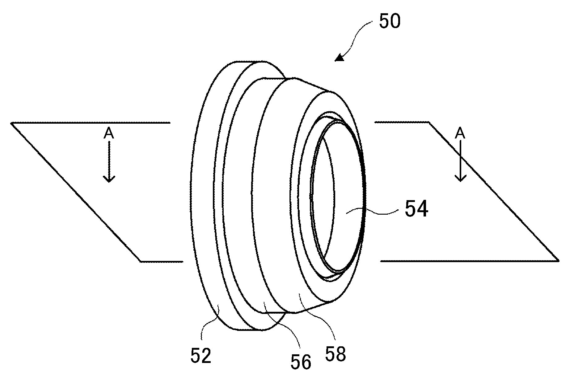
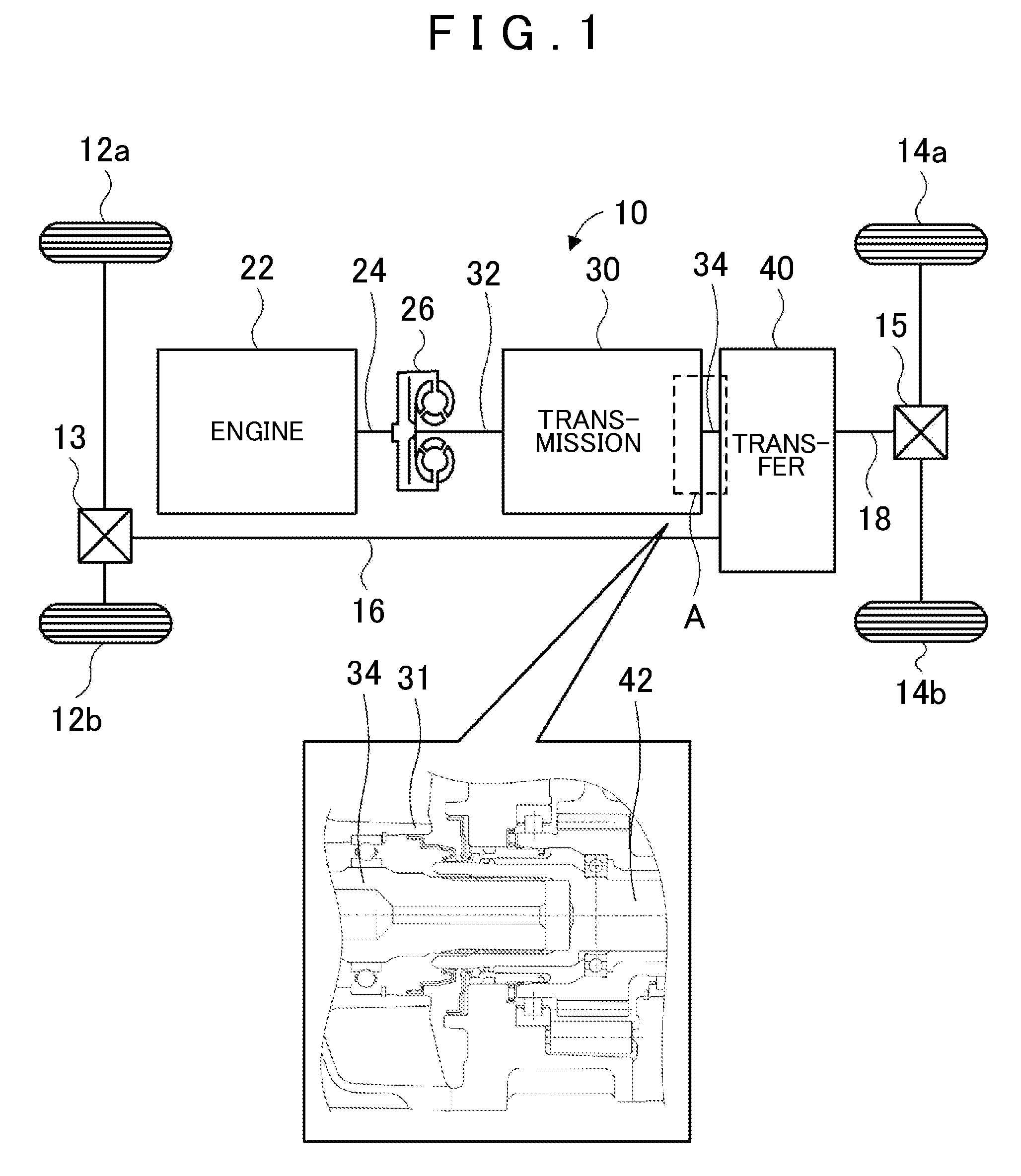
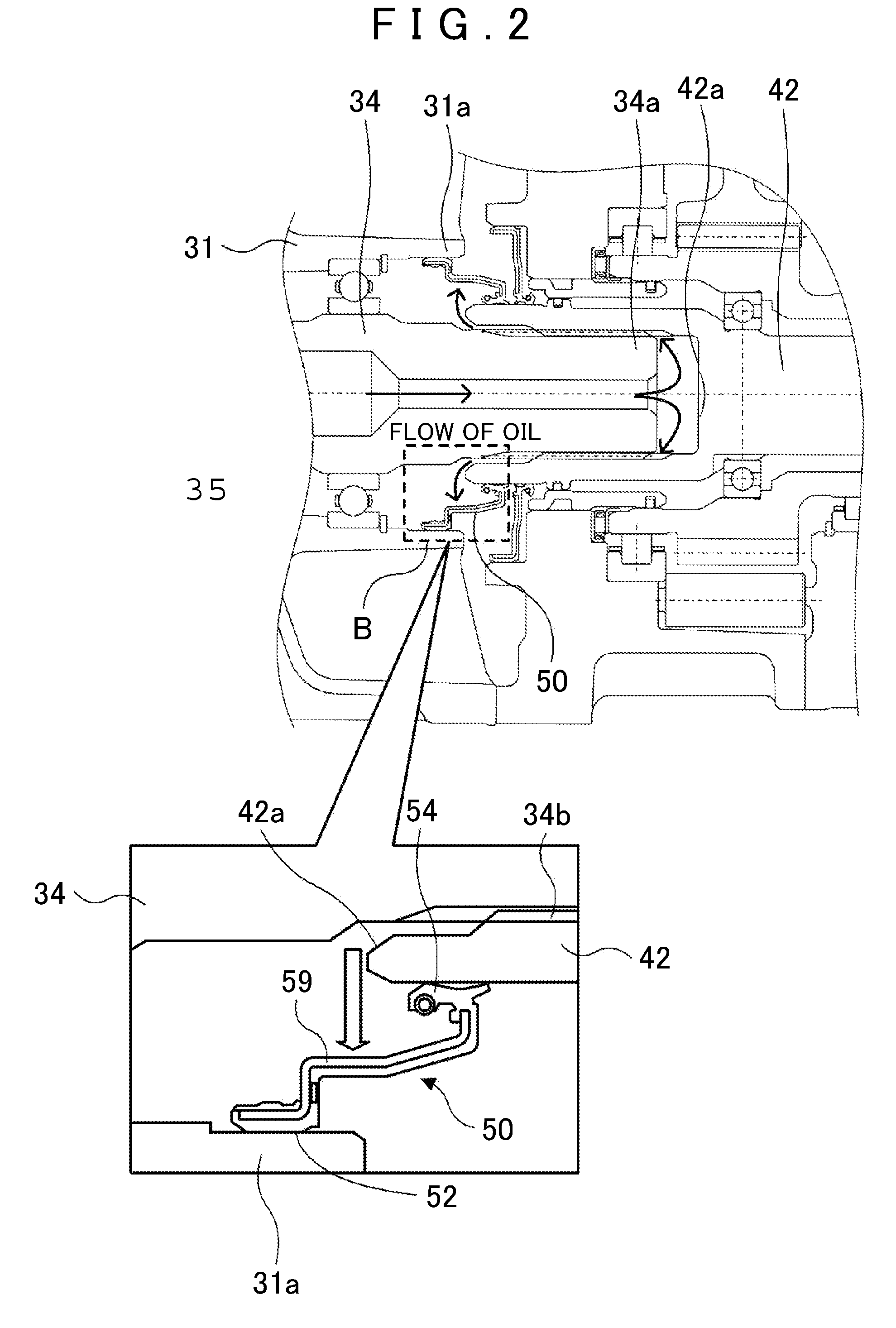
[0020]FIG. 1 is a block diagram showing an outline of the constitution of an automobile 10 installed with a power transmission apparatus serving as an exemplary embodiment of the present invention, and FIG. 2 is an enlarged view of an A region of the power transmission apparatus shown in FIG. 1. As shown in the drawings, the automobile 10 according to this embodiment includes an engine 22 (for example, an internal combustion engine that outputs motive power by subjecting a hydrocarbon-based fuel such as gasoline or light oil to explosive combustion), a torque converter 26 attached to a crankshaft 24 of the engine 22, a transmission 30 having an input shaft 32 that is connected to an output side of the torque converter 26 for shifting the motive power from the torque converter 26 and transmitting the shifted motive power to an output shaft 34, and a transfer 40 having an input shaft 42 that is connected to...


PUM


Abstract

An oil seal for sealing a hollow rotary shaft in a power transmission apparatus, wherein the rotary shaft is formed with an internal flow passage through which oil flows and constituted such that the oil flies out as the rotary shaft rotates, including: a fixed portion that is fixedly attached to a case of the power transmission apparatus; a seal portion that seals the rotary shaft at a position that is axially offset position from the fixed portion and allows the rotary shaft to rotate; and a radiator portion that is formed from a metallic material between the fixed portion and the seal portion, receives the oil that flies out as the rotary shaft rotates, and dissipates heat generated by the seal portion by exchanging heat with the oil.

Description

INCORPORATION BY REFERENCE[0001]This Application claims priority from Japanese Patent Application No. 2008-090111, filed on Mar. 31, 2008, the disclosure, including the specification, drawings, and abstract, of which is incorporated herein by reference in its entirety.BACKGROUND OF THE INVENTION[0002]The present invention relates to an oil seal and a power transmission apparatus. More particularly, the present invention relates to an oil seal for sealing a hollow rotary shaft in a power transmission apparatus in which the rotary shaft is formed with an internal flow passage through which oil flows and constituted such that the oil flies out as the rotary shaft rotates and a power transmission apparatus in which the rotary shaft is sealed using the oil seal.DESCRIPTION OF THE RELATED ART [0003]The related art has proposed a power transmission apparatus having an automatic transmission including a hollow output shaft formed with an internal flow passage through which lubricating oil f...

Claims


Application Information

Patent Timeline
Patent Type & Authority Applications(United States)
IPC IPC(8): F16J15/32F16C3/00F16C33/72F16H57/04F16J15/324
CPCF16J15/3252
Inventor OMAGARI, KAZUTOSHIFUKUOKA, TERUHITONAGAI, KENJINAGASE, NARUHITOHABATA, YOUHEIMIZUTA, HIROYATANAKA, MASAHARU
Owner AISIN AW CO LTD
Why Eureka
Try Eureka