System and method for monitoring current in a conductor

Inactive Publication Date: 2009-10-01
GENERAL ELECTRIC CO
View PDF9 Cites 37 Cited by
  • Summary
  • Abstract
  • Description
  • Claims
  • Application Information

AI Technical Summary

Benefits of technology

[0006]Accordingly, there is a need for a relatively sim

Problems solved by technology

However, this disclosure fails to provide adequate means for external noise cancellation.
However, this circuitry results in significantly reduced coil densities, making the design less appropriate for low frequency (at about 50/60 Hz) current measurement applications.
In addition, although improved, all reported geometries suffer from Z-a

Method used


Image

  • System and method for monitoring current in a conductor
  • System and method for monitoring current in a conductor
  • System and method for monitoring current in a conductor

Examples


Embodiment Construction

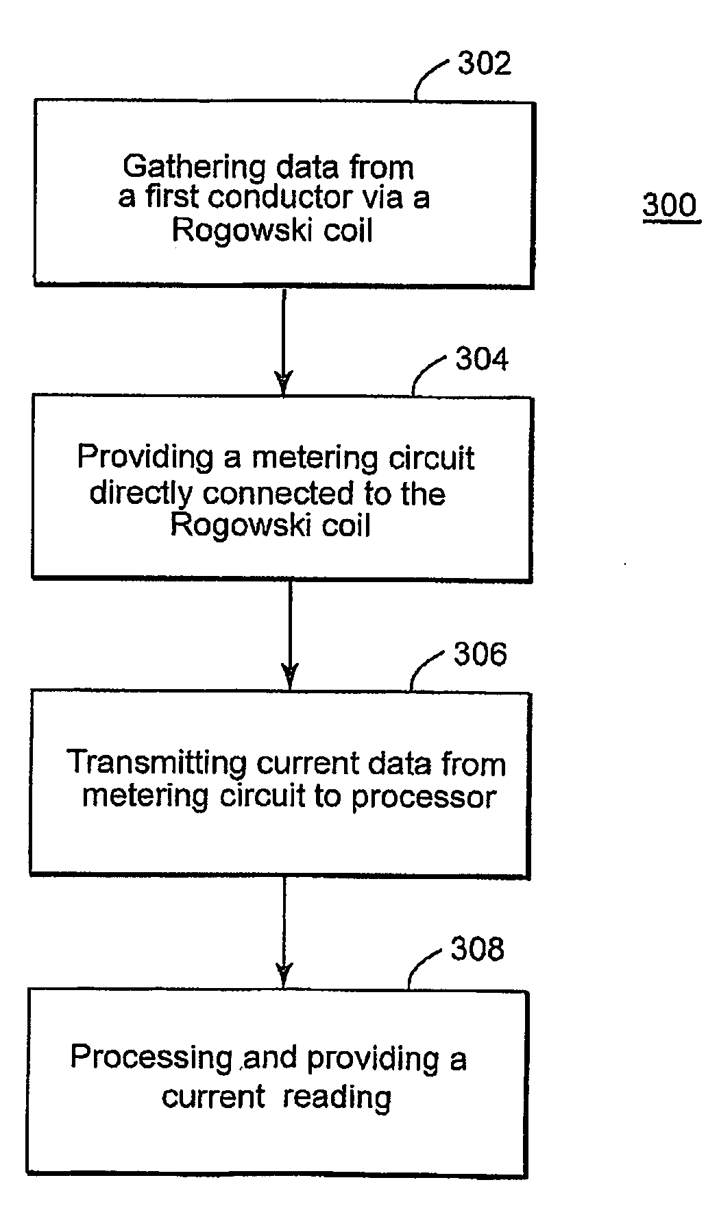
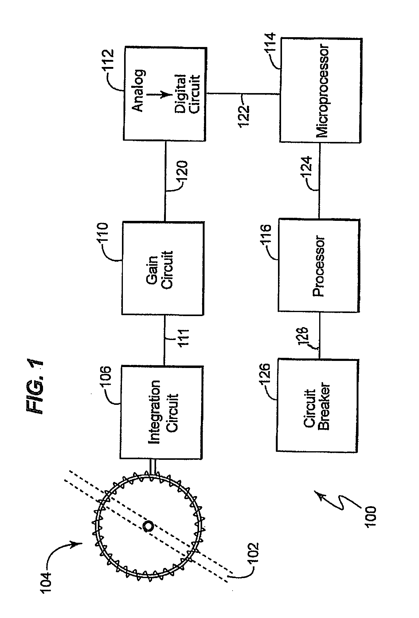
[0015]An embodiment of the present invention involves a current monitoring system which comprises at least one Rogowski coil and a metering / integration circuit attached to the Rogowski coil which outputs current amplitude data for input to a processor. One particular advantage afforded by this invention is increased noise reduction and decreased signal degradation in Rogowski coil circuitry.

[0016]Specific configurations and arrangements of the claimed invention, discussed below with reference to the accompanying drawings, are for illustrative purposes only. Other configurations and arrangements that are within the purview of a skilled artisan can be made, used, or sold without departing from the spirit and scope of the appended claims. For example, while some embodiments of the invention are herein described with reference to a commercial plant site, a skilled artisan will recognize that embodiments of the invention can be implemented in any setting in which remote energy data monit...


PUM


Abstract

The present disclosure describes a system for measuring current amplitude in a conductor, comprising at least one Rogowski coil, an integration circuit directly connected to the at least one Rogowski coil, a microprocessor circuit in communication with the integration circuit and configured to receive output from the integration circuit and to calculate energy data comprising current amplitude in the conductor. A method for measuring current in a conductor is also presented.

Description

BACKGROUND[0001]The present invention relates to a system, apparatus and method for monitoring energy data. More specifically, the invention relates to monitoring electrical current amplitude.[0002]Rogowski coils are useful for measuring electrical currents flowing through a conductor. The Rogowski coil provides a voltage output that is proportional to the time derivative of the current (di / dt), rather than a current output like traditional current transformers. One particular advantage of a Rogowski coil is that it does not suffer from voltage saturation and is therefore useful over a wide current range.[0003]One known approach to making a Rogowski coil involves using a printed circuit. For example, U.S. Pat. No. 5,414,400 describes a Rogowski coil implemented on a printed circuit plate provided with a circular cut-out. The coil is implemented by metal deposits on each of the two faces of the plate extending along radii, with electrical connections between the radii on one face and...

Claims


Application Information

Patent Timeline
IPC IPC(8): G01R19/00
CPCG01R19/04G01R15/181
Inventor WEST, STEPHEN JAMESVICENTE, NATANIEL BARBOSALENHART, BRIAN PATRICKGREENWOOD, TODDHAMEED, ZUBAIRDEVARAPALLI, SREENIVASULU
Owner GENERAL ELECTRIC CO
Why Eureka
Try Eureka