Current probe

a current probe and current technology, applied in the field of current probes, can solve the problems of low sensitivity at low frequency, inability to measure dc current, low sensitivity for a current of dc or low frequency, etc., and achieve the effect of generating magnetic flux

Active Publication Date: 2005-04-26
TEKTRONIX INC
View PDF6 Cites 31 Cited by
  • Summary
  • Abstract
  • Description
  • Claims
  • Application Information

AI Technical Summary

Benefits of technology

[0012]The first current detecting means may further have a shield means for magnetically shielding the orthogonal fluxgate element from external magnetic field. The feedback coil may wind around the shield means which serves as a magnetic core so that the feedback coil more effectively generates the magnetic flux to cancel the magnetic flux generated in the induced voltage detecting means by the current under test.

Problems solved by technology

If the metal bus bar is intricately wired, a desired line under test of the bus bar may not be in a position for putting it through a detecting portion of the current probe.
A drawback to the Rogowski coil, however, is that it cannot measure DC current and has low sensitivity at low frequency.
As described, the flexibility of the Rogowski coil is suitable for measuring a large current, but has low sensitivity for a current of DC or low frequency.

Method used


Image

  • Current probe
  • Current probe
  • Current probe

Examples


Embodiment Construction

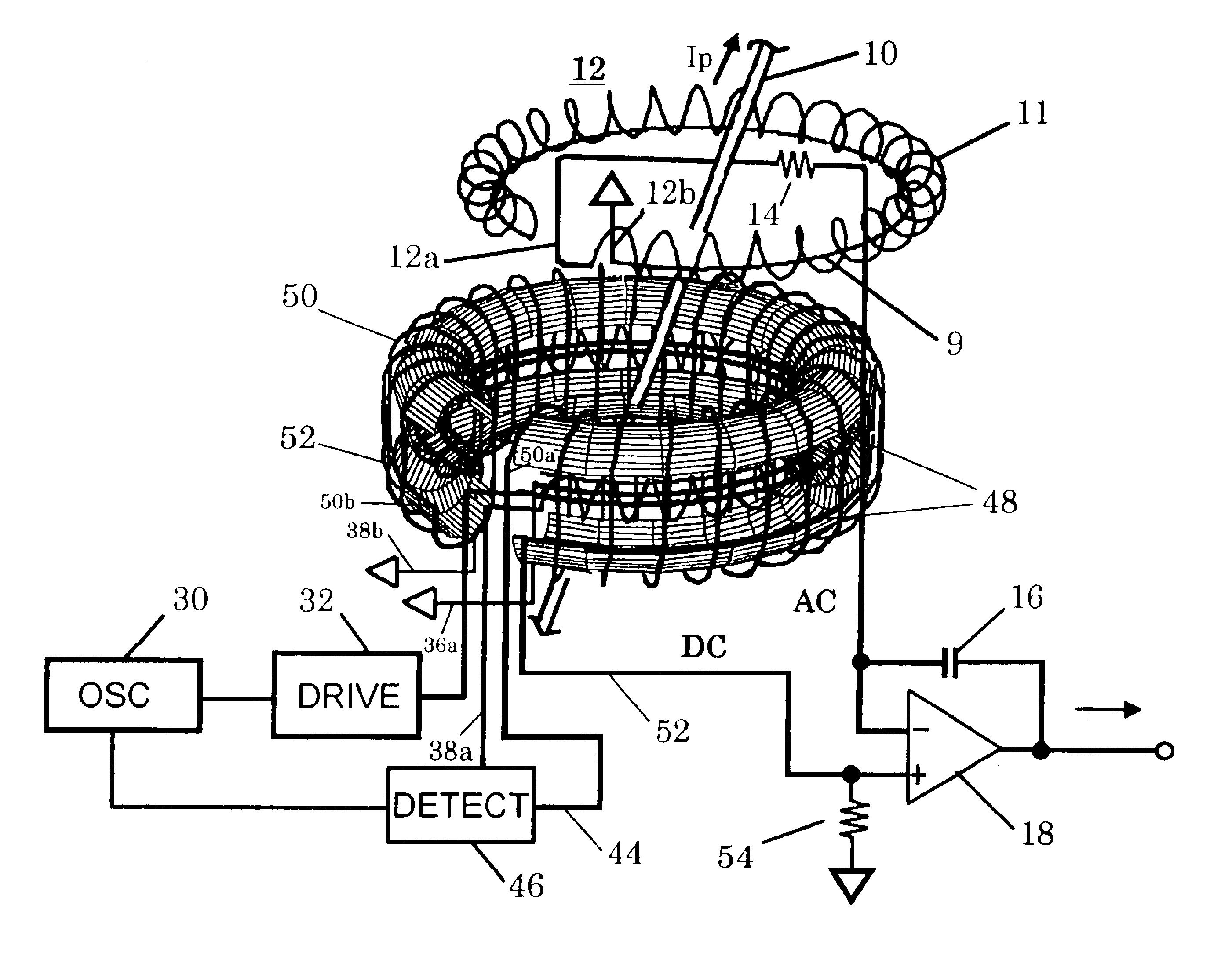
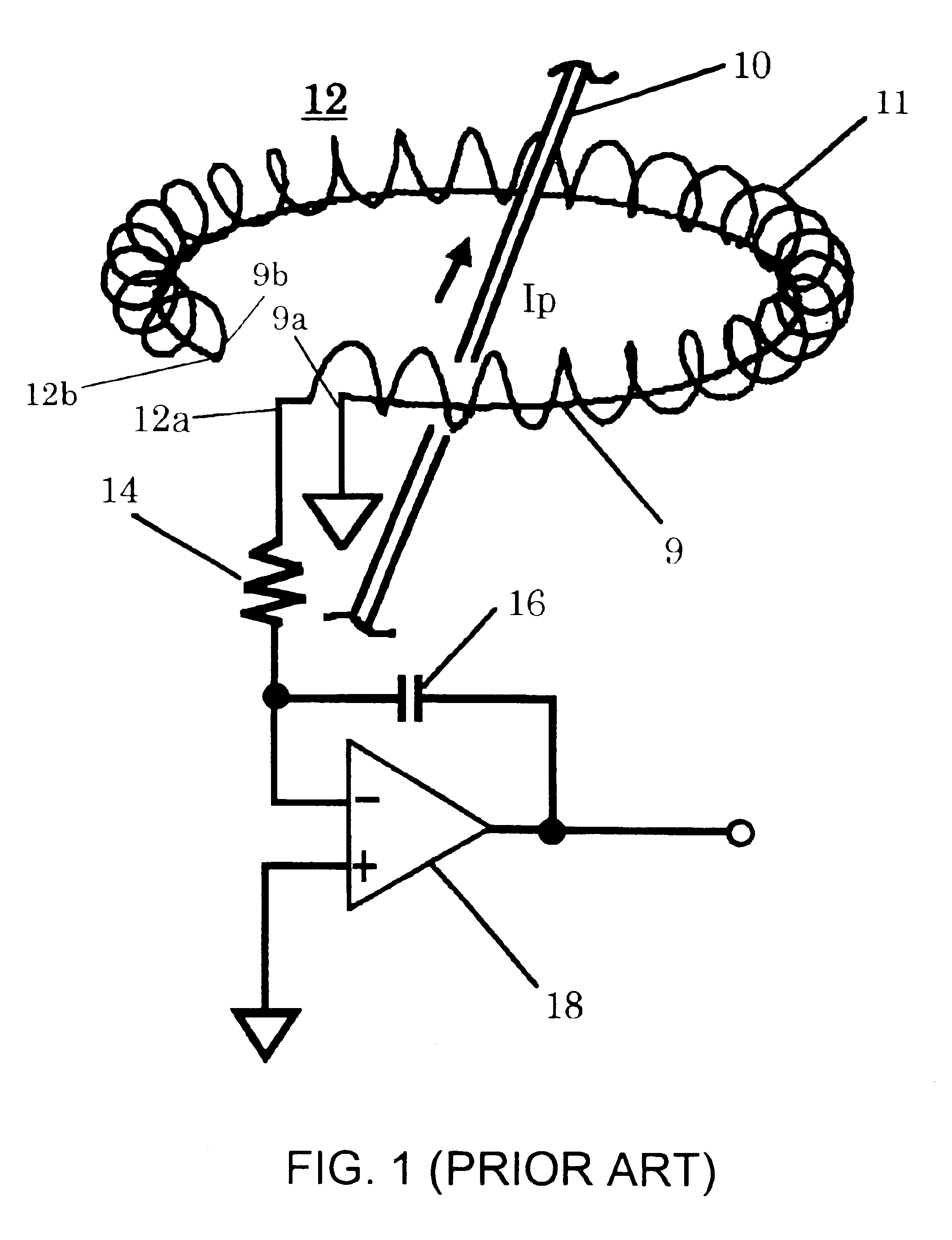
[0023]A current probe according to the present invention has first and second current detecting means. The first current detecting means mainly detects a current under test in a low frequency band (a first frequency band) from DC to a predetermined intermediate frequency band. The second current detecting means mainly detects the current under test in a frequency band (a second frequency band) that is higher than the predetermined intermediate frequency band. The main component of the first current detecting means is an orthogonal fluxgate element. The main component of the second current detecting means is a Rogowski coil. The predetermined intermediate frequency band is a boundary band covering the end of the first frequency band and the start of the second frequency band measured by the first and second current detecting means. The predetermined intermediate frequency band is determined as a function of the frequency characteristics of the first and second current detecting means...


PUM


Abstract

A current probe suitable for detecting a large current from DC to high frequency has first and second current detecting means. The first current detecting means detects a current under test from DC to a predetermined intermediate frequency band. It has an orthogonal flux gate element, an induced voltage detecting circuit 46 for detecting an induced voltage of the orthogonal fluxgate element, and a feedback coil 50 receiving the output voltage of the induced voltage detecting circuit 46 for generating magnetic flux to cancel the magnetic flux generated by the current under test. The second current detecting means has a Rogowski coil 12 and an integration circuit and detects said current under test higher than the predetermined intermediate frequency band.

Description

BACKGROUND OF THE INVENTION[0001]The present invention relates generally to current probes and more particularly to a current probe suitable for detecting wide bandwidth large currents from DC to high frequencies using an orthogonal fluxgate magnetic sensor and a Rogowski coil.[0002]A current probe is used to detect a current signal flowing in a line under test, such as a cable. A current probe using a transformer is suitable for detecting a relatively weak current in the micro or milliamp range. However, for high currents in the kilo or mega-amps, a current detecting circuit using a Rogowski coil would be suitable. The Rogowski coil does not require the use of a magnetic core and thus the size is smaller than a corresponding transformer rated for such currents.[0003]FIG. 1 shows a schematic block diagram of a current detecting circuit using the Rogowski coil. The Rogowski coil 12 has a detecting coil 11 and a conducting return wire 9 formed from a single piece of wire 13. The wire ...

Claims


Application Information

Patent Timeline
Patent Type & Authority Patents(United States)
IPC IPC(8): G01R15/14G01R15/18G01R19/00
CPCG01R15/185G01R15/181
Inventor KATO, KATSUHISA
Owner TEKTRONIX INC
Why Eureka
Try Eureka