Four-terminal electric imager for resistive muds with localized current control

Active Publication Date: 2009-10-01
BAKER HUGHES INC
View PDF6 Cites 17 Cited by
  • Summary
  • Abstract
  • Description
  • Claims
  • Application Information

AI Technical Summary

Benefits of technology

[0022]FIGS. 4A and 4B, collectively referred to as FIG. 4, illustrate an exemplary emb

Problems solved by technology

The drawback is that the imager 99 h

Method used


Image

  • Four-terminal electric imager for resistive muds with localized current control
  • Four-terminal electric imager for resistive muds with localized current control
  • Four-terminal electric imager for resistive muds with localized current control

Examples


Embodiment Construction

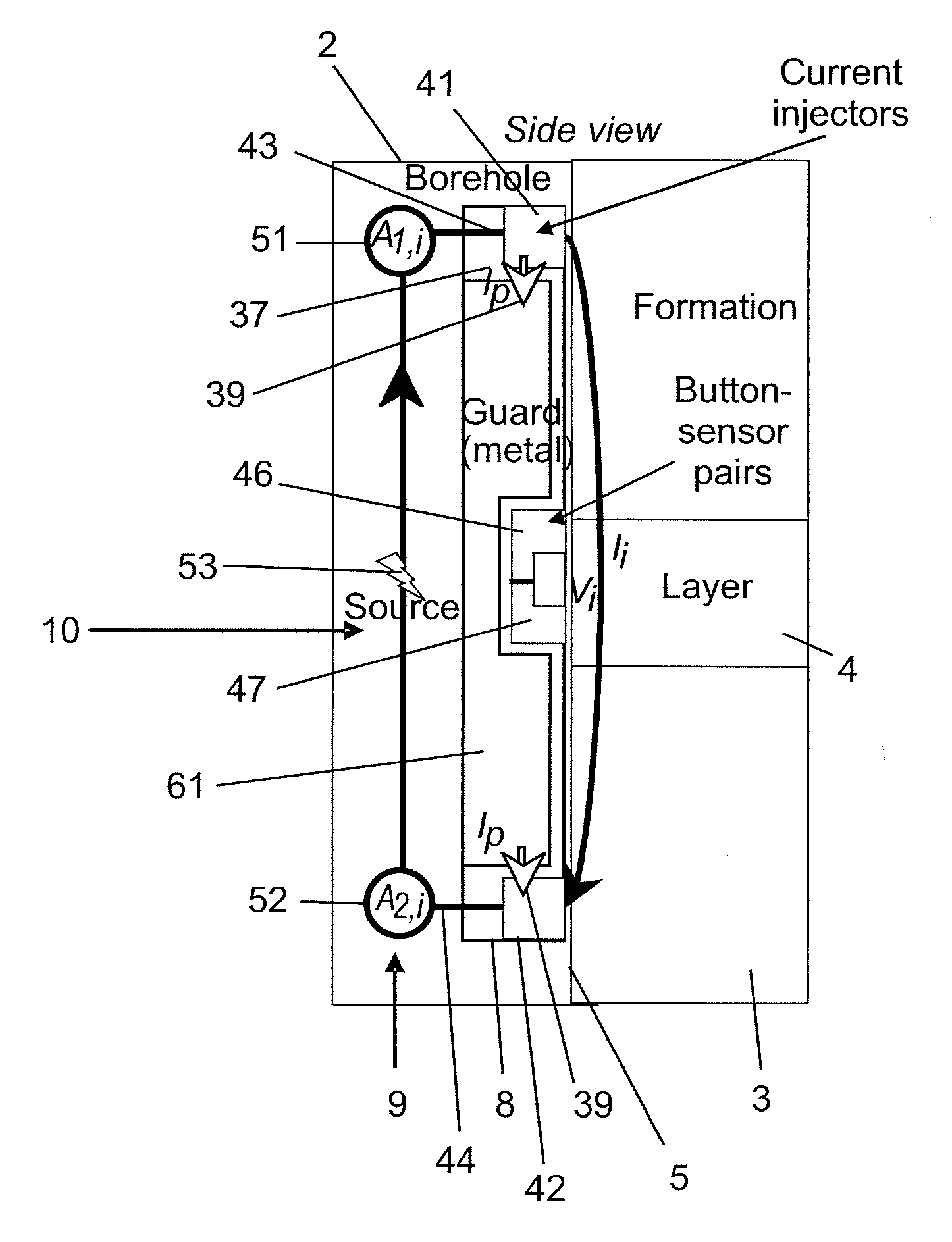
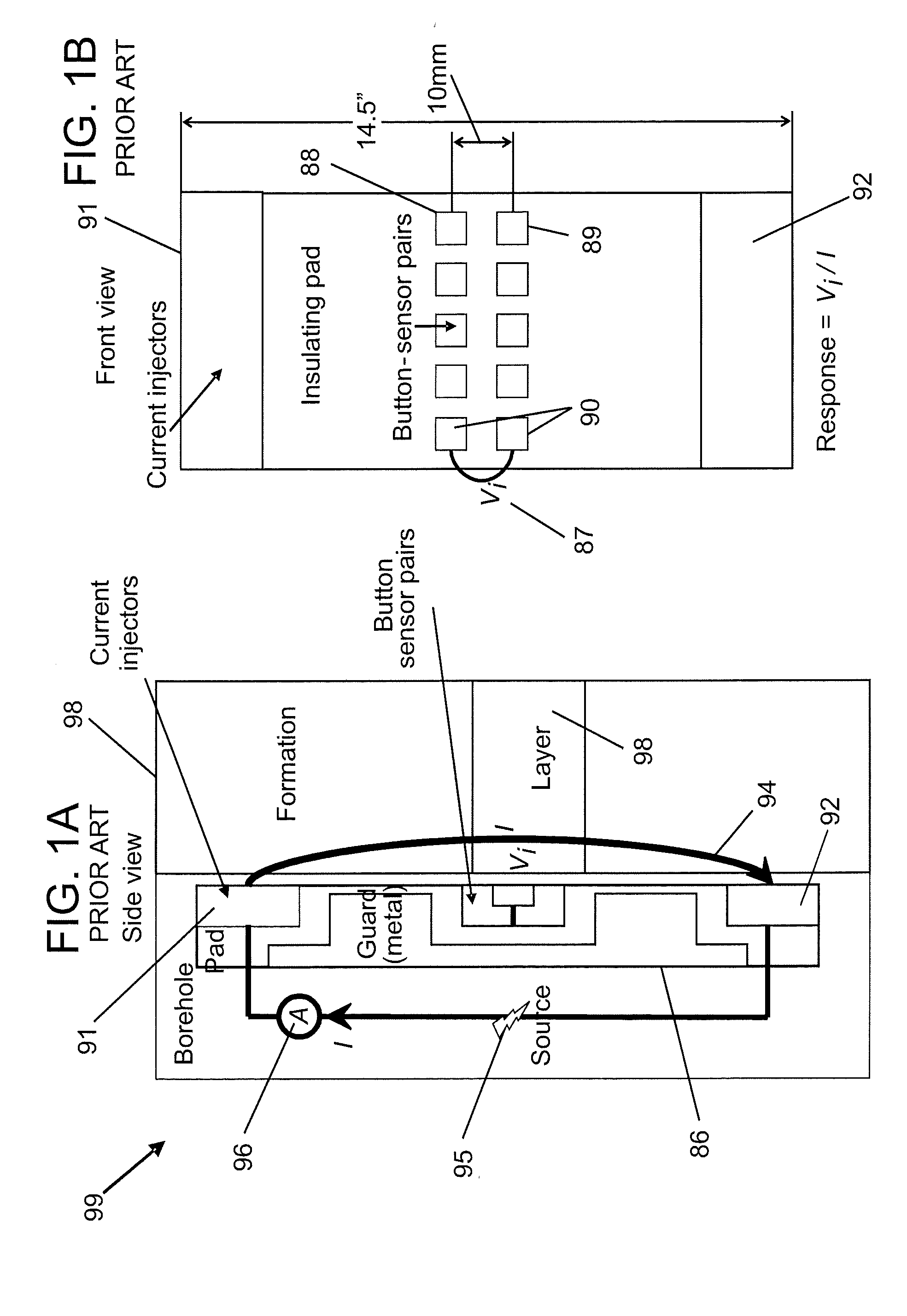
[0032]The teachings provide techniques for imaging a formation from a borehole. The techniques provide embodiments of apparatus and a method for measuring a property of the formation (such as resistivity) with high azimuthal resolution to provide an image of the formation with high azimuthal resolution.

[0033]The techniques call for apparatus that includes a plurality of current injector electrode pairs and a plurality of button-sensor pairs. In the apparatus, each button-sensor electrode pair is disposed between a pair of current injector electrodes. One current injector electrode pair and one associated button-sensor electrode pair is referred to as a “measurement set.” Use of a plurality of measurement sets on an imaging pad provides for measurements of resistivity with high azimuthal resolution. The teachings are applicable to wireline logging and logging-while-drilling (LWD) applications.

[0034]Certain definitions are provided for convenience. The term “azimuthal resolution” rela...


PUM


Abstract

An apparatus for imaging a subsurface material traversed by a borehole, the apparatus including an imaging pad deployed by a logging instrument, the pad including a plurality of measuring sets, each measuring set including a first current injector electrode, a second current injector electrode, a pair of sensor electrodes disposed between the first current injector electrode and the second current injector electrode, and an output for coupling to an electronics unit adapted for producing the imaging of the subsurface material.

Description

BACKGROUND OF THE INVENTION[0001]1. Field of the Invention[0002]The invention disclosed herein relates to imaging a subsurface material from a borehole.[0003]2. Description of the Related Art[0004]In exploration for hydrocarbons, it is important to make accurate measurements of various properties of geologic formations. In particular, it is important to determine the various properties with a high degree of accuracy so that drilling resources are used efficiently.[0005]Generally, oil and gas are accessed by drilling boreholes into the subsurface of the earth. The boreholes also provide access for taking measurements of the geologic formations.[0006]Well logging is a technique used to take measurements of the geologic formations from the boreholes. In one embodiment, a “logging instrument” is lowered on the end of a wireline into a borehole. The logging instrument sends data via the wireline to the surface for recording. Output from the logging instrument comes in various forms and m...

Claims


Application Information

Patent Timeline
IPC IPC(8): G01V3/24
CPCG01V3/24
Inventor BESPALOV, ALEXANDRE N.BEARD, DAVID R.GOLD, RANDYITSKOVICH, GREGORY B.WANG, TSILI
Owner BAKER HUGHES INC
Why Eureka
Try Eureka