Output driving device

a driving device and output technology, applied in pulse generators, pulse manipulation, pulse techniques, etc., can solve the problems of inefficient driving power of the output driving device shown in fig. 4 and the limitation of the output driving device of the conventional output driving devi

Inactive Publication Date: 2009-10-01
SK HYNIX INC
View PDF6 Cites 8 Cited by
  • Summary
  • Abstract
  • Description
  • Claims
  • Application Information

AI Technical Summary

Benefits of technology

[0025]Embodiments of the present invention are directed to provide an output driving device which is capabl

Problems solved by technology

However, the driving power of the output driving device shown in FIG. 4 is inefficient because the driving power is set based upon the largest transistor in order to drive the PMOS transistors and the NMOS transistor

Method used


Image

  • Output driving device
  • Output driving device
  • Output driving device

Examples


Embodiment Construction

[0036]Other objects and advantages of the present invention can be understood by the following description, and become apparent with reference to the embodiments of the present invention.

[0037]Hereinafter, an output driving device in accordance with an embodiment of the present invention will be described in detail.

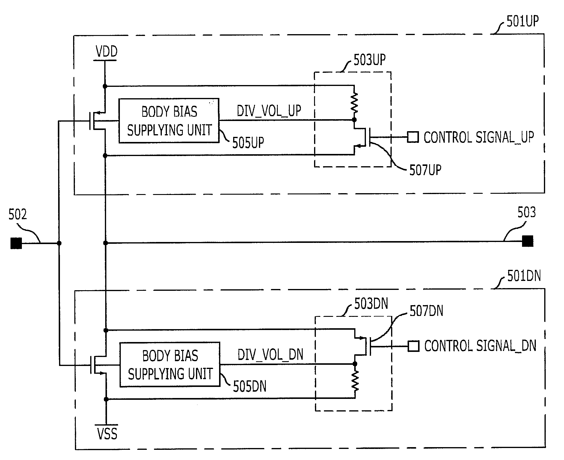
[0038]FIG. 5 is a structural diagram of an output driving device in accordance with an embodiment of the present invention.

[0039]Referring to FIG. 5, the output driving device in accordance with the embodiment of the present invention includes a pull-up driving unit 501UP and a pull-down driving unit 501DN, which are provided between an input line 502 and an output line 503.

[0040]The pull-up driving unit 501UP includes a PMOS transistor and a first body bias controller. The PMOS transistor has a source connected to a power supply voltage terminal VDD, a drain connected to the output line 503, and a gate connected to the input line 502. The first body bias controller is co...


PUM


Abstract

An output driving device capable of improving a slew rate is provided. The output driving device includes a push-pull type driving unit configured with a pull-up PMOS transistor and a pull-down NMOS transistor, wherein body biases of the pull-up PMOS transistor and the pull-down NMOS transistor are controlled for control of a slew rate of an output signal of the driving unit.

Description

CROSS-REFERENCES TO RELATED APPLICATIONS[0001]The present invention claims priority of Korean patent application numbers 10-2008-0027798 and 10-2008-0134937, filed on Mar. 26, 2008, and Dec. 26, 2008, respectively, disclosures of which are incorporated herein by reference in their entireties.BACKGROUND OF THE INVENTION[0002]The present invention relates to an output driving device used in a semiconductor memory device, and more particularly, to an output driving device which is capable of improving a slew rate.[0003]Push-pull type drivers are widely used in buffers and driving amplifiers of semiconductor memory devices. In the push-pull type drivers, the control of the slew rate is very important.[0004]A slew rate is defined as a maximum change rate of an output voltage per unit time. For example, in the case of an output driving device with a gain of 1, an input voltage immediately rises from 0 V to 1 V in an ideal circuit. However, in a practical circuit, when a slew rate is K, an...

Claims


Application Information

Patent Timeline
IPC IPC(8): H03K3/00
CPCH03K19/0027H03K2217/0018H03K2005/00123H03K19/00323
Inventor PARK, CHANG-KUNKIM, YONG-JUHAN, SUNG-WOOSONG, HEE-WOONGOH, IC-SUKIM, HYUNG-SOOHWANG, TAE-JINCHOI, HAE-RANGLEE, JI-WANGJANG, JAE-MIN
Owner SK HYNIX INC
Why Eureka
Try Eureka