
Method and device for positioning aircraft, such as for automatic guiding during the landing phase

a technology for positioning aircraft and landing phase, applied in measurement devices, using reradiation, instruments, etc., can solve problems such as inability to meet the requirements of the landing phase, and inability to provide all-weather performance of laser-based solutions, etc., to achieve reliable positioning and simple implementation

Inactive Publication Date: 2009-10-01
THALES SA
View PDF10 Cites 16 Cited by
  • Summary
  • Abstract
  • Description
  • Claims
  • Application Information

AI Technical Summary

Benefits of technology

The invention is a method and device for locating an aircraft using radar and airborne beacons. The radar performs initial distance and angle location, while the beacons on the aircraft and at predetermined positions provide additional information to refine the location. The method is simple, economical, and reliable. The device includes a radar and beacons for distance and angle location, with the radar performing the initial measurement and the beacons providing additional information for refinement. The invention has various embodiments and modifications can be made to the details without changing the main idea.

Problems solved by technology

This solution poses the problem of service availability or continuity.
Additionally its vulnerability in the presence of jammers is known.
This laser-based solution does not offer all-weather performance.
This radar solution which calls upon conventional tracking radar techniques in particular those using radars with servomechanisms, are expensive and difficult to implement.
In particular, in the event of multiple objectives, it is necessary to share the time and operate target-to-target homing at the risk of losing a target and of having to effect complete acquisition of the context.
In the approach phase, the guidance constraints for keeping the target in the radar beam are very significant.
The consequences of losing this target can be dramatic.
Finally, having regard to propagation losses in the millimetre domain, it is necessary to use a transponder onboard the drone, this transponder transmitting permanently, which is not prudent.
It should also be added that the presence of this transponder decreases the reliability of the guidance system.
Specifically, in the event of transponder failure, there is a break in the downlink from the transponder to the radar, thereby blinding the radar.

Method used


Image

  • Method and device for positioning aircraft, such as for automatic guiding during the landing phase
  • Method and device for positioning aircraft, such as for automatic guiding during the landing phase
  • Method and device for positioning aircraft, such as for automatic guiding during the landing phase

Examples


Embodiment Construction

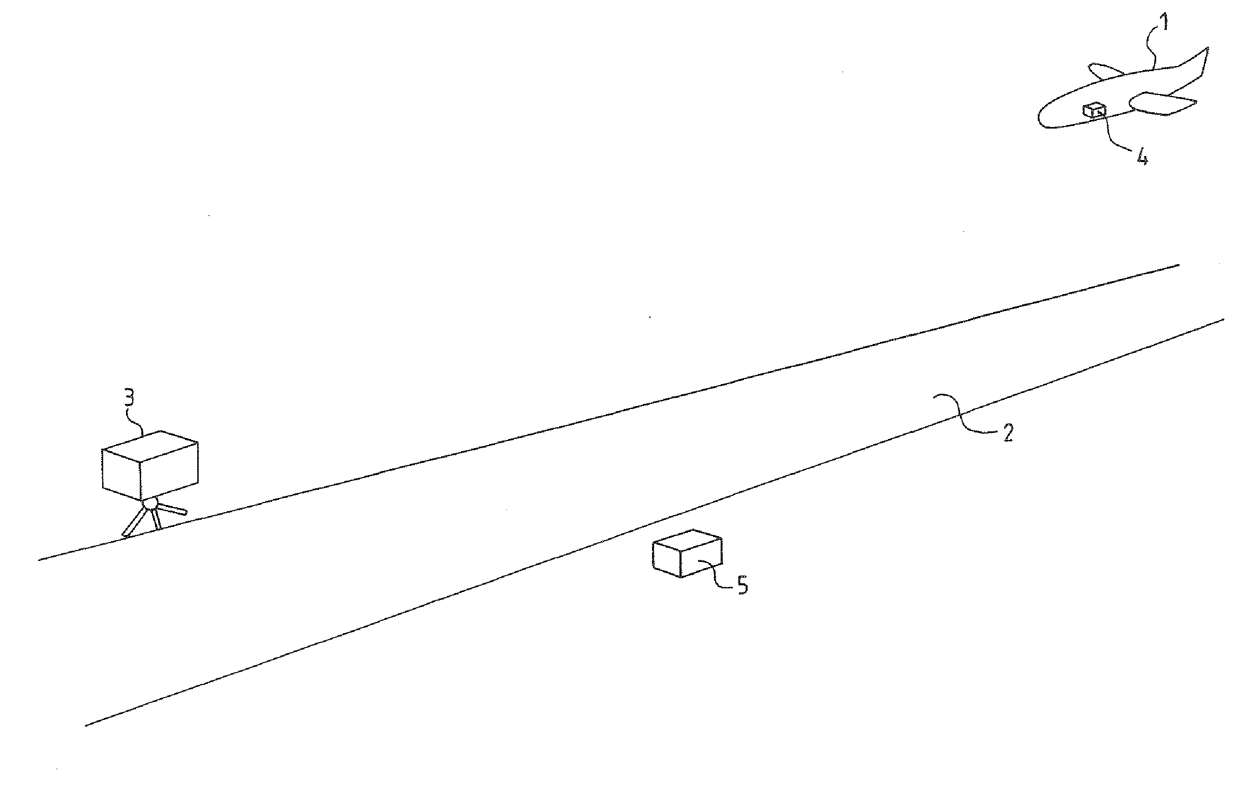
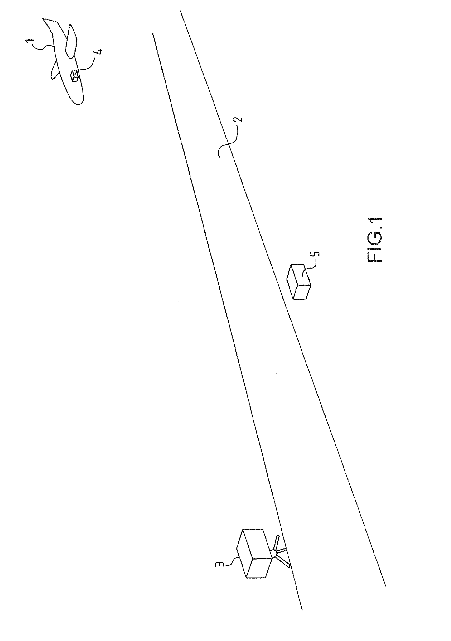
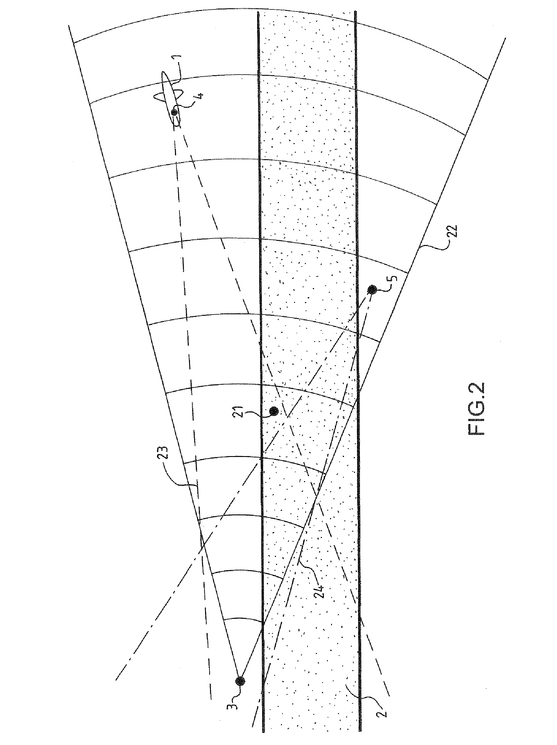
[0024]FIG. 1 presents an aircraft 1 in the phase of landing on a runway 2. Subsequently, it will be considered by way of example that the aircraft is a drone. Additionally, FIG. 1 illustrates elements of a device according to the invention. The device comprises at least:[0025]a ground radar 3, preferably with a wide detection cone, for example of the order of 20°;[0026]an airborne beacon 4 onboard the drone 1, this beacon makes it possible in particular for the target formed by the drone to be rendered point-like;[0027]a ground beacon 5 which serves in particular as reference, as will be shown subsequently.

[0028]These elements make it possible to calculate the position of the drone up to complete landing. The drone is thereafter guided by conventional guidance means on the basis of its calculated position. The radar 3 and the ground beacon 5 are disposed in proximity to the runway 2.

[0029]In the approach phase, the drone penetrates into the lobe of the antenna of the radar 3. The st...


PUM


Abstract

The present invention relates to a method and a device for locating aircraft. A radar (3) performs distance and angle location of the aircraft. Location is refined by means of at least one airborne beacon (4) aboard the aircraft and of at least one beacon (5) whose position is predetermined with respect to the radar (3), the measurement of the position of the airborne beacon (4) being performed by the radar (3) by differential measurement between the position of at least one ground beacon (5) and of at least one airborne beacon (4). The invention is in particular used for the automatic guidance of drones in the approach and landing phase.

Description

CROSS-REFERENCE TO RELATED APPLICATIONS[0001]The present Application is based on International Application No. PCT / EP2005 / 055975, filed on Nov. 15, 2005, which in turn corresponds to French Application No. 04 12313, filed on Nov. 19, 2004, and priority is hereby claimed under 35 USC §119 based on these applications. Each of these applications are hereby incorporated by reference in their entirety into the present application.FIELD OF THE INVENTION[0002]The present invention relates to a method and a device for locating aircraft, in particular for their automatic guidance in the landing phase. The invention relates for example to the guidance of drones in the approach and landing phase.BACKGROUND OF THE INVENTION[0003]Solutions are known for automatically guiding aircraft, in particular drones, in the landing phase. A first solution uses the GPS (Global Positioning System) or DGPS (Differential Global Positioning System). This solution poses the problem of service availability or con...

Claims


Application Information

Patent Timeline
Patent Type & Authority Applications(United States)
IPC IPC(8): G01S13/91
CPCG01S7/40G01S7/4056G01S13/44G01S13/762G01S2007/4091G01S13/78G01S13/825G01S13/913G01S7/4052G01S13/765G01S7/4091
Inventor CORNIC, PASCALGARREC, PATRICKLACOMME, PHILIPPE
Owner THALES SA
Learn More