Epicardial ablation using focused ultrasound

a technology of ultrasound and epicardial valve, applied in the field of epicardial valve, can solve the problems of thrombogenesis or blood clotting, unsatisfactory contraction of muscle constituting muscle, and reducing the pumping efficiency of the hear

Inactive Publication Date: 2009-10-01
TRANSURGICAL INC
View PDF16 Cites 20 Cited by
  • Summary
  • Abstract
  • Description
  • Claims
  • Application Information

AI Technical Summary

Problems solved by technology

For example, in atrial fibrillation, abnormal signals conducted along abnormal pathways in the vicinity of the pulmonary veins cause undesired contraction of the muscle constituting the left atrium out of synchronization with the remainder of the cardiac cycle.
Arrhythmias decrease the pumping efficiency of the heart, and can cause thrombogenesis or clotting of the blood.
Radiofrequency ablation has significant drawbacks, including scarring of the delicate lining of the heart leading to thrombogenesis.
However, simple ultrasonic transducers of a size which can be practically mounted on such a probe can provide only a very limited power density in the tissue being heated.
Therefore, considerable time is required to heat the particular tissue to be ablated.
This, in turn, leads to substantial conduction of heat to neighboring tissues, making it difficult or impossible to heat tissue within the wall of the heart without also damaging surrounding tissues.
Although the '543 patent mentions that the ablation probe can use RF, ultrasound, microwave, laser, heat, chemical agents, biological agents and light-activated agents, it does not provide a practical way of ablating the myocardial tissue from outside of the heart using ultrasound.
The '285 patent also mentions briefly that “other ablation means, such as RF heating, cryogenic cooling, ultrasound, microwave, ablative fluid injection and the like” can be used, but provides no practical way of forming a lesion using ultrasonic energy.
The '767 patent mentions that the ablation elements may be RF, ultrasound, laser or cryogenic elements, but here again, fails to provide any practical way of applying ultrasonic energy to produce a transmural lesion.

Method used


Image

  • Epicardial ablation using focused ultrasound
  • Epicardial ablation using focused ultrasound
  • Epicardial ablation using focused ultrasound

Examples


Embodiment Construction

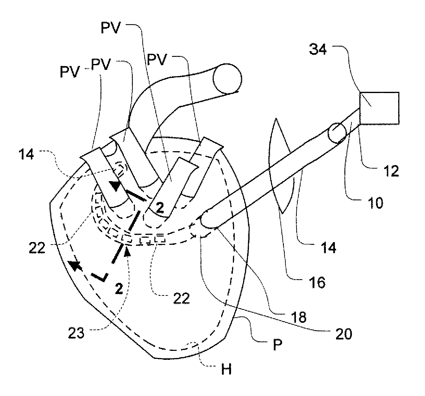
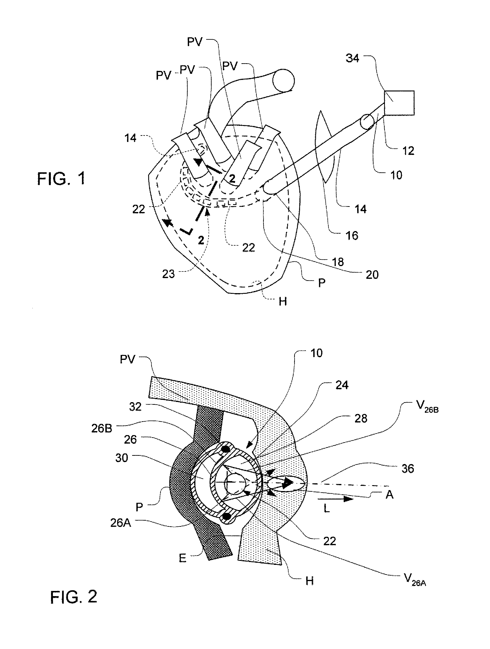
[0025]As seen in FIG. 1, apparatus in accordance with one embodiment of the present invention incorporates an elongated rod-like probe 10 having a proximal end 12 and a distal end 14, and having a lengthwise direction extending between these ends. The apparatus also includes a hollow tubular insertion guide 14 which may be a simple sheath or a trocar. Introducer 14 is dimensioned and constructed so that it can be inserted into the patient's body through a subxiphoid insertion into the pericardial sack P, so as to position the distal end 20 of the introducer 14 inside the pericardial sack. In FIG. 1, the structures enclosed by the pericardial sack are indicated in broken lines for clarity of illustration. Also, FIG. 1 depicts the pericardial sack P and other structures of the patient's heart H in an entirely schematic form.

[0026]Probe 10 has a large number of individual ultrasonic emitting elements 22 disposed along the length of the probe within an emitting region 23 near the distal...


PUM


Abstract

Apparatus for treating cardiac arrhythmias includes an ultrasonic ablation device incorporating an ultrasonic emitter (22, 400), means (10, 14, 402, 404) for positioning the ablation device outside of the heart but adjacent the epicardial surface of the heart, and means (26, 28, 30) for focusing the ultrasonic energy emitted by the emitter into an ablation region, so that the ablation region is disposed within the wall of the heart.

Description

CROSS-REFERENCE TO RELATED APPLICATIONS[0001]The present application is a continuation of U.S. patent application Ser. No. 11 / 324,542, filed Jan. 3, 2006, which application claims the benefit of the filing date of U.S. Provisional Patent Application No. 60 / 643,281, filed Jan. 12, 2005, the disclosures of which are hereby incorporated by reference herein.BACKGROUND OF THE INVENTION[0002]The present invention relates to apparatus and methods for cardiac ablation.[0003]The repetitive contraction of the heart is controlled by electrical signals propagating within the tissue of the heart itself. In a normal heart, these signals travel along well-defined pathways in a controlled manner, so that the various portions of the heart muscle contract in a well-defined rhythm. In diseased states referred to as cardiac arrhythmias, the normal pattern of conduction is disrupted, typically by the presence of abnormal signal sources, conductive pathways or both, which cause abnormal signals to propag...

Claims


Application Information

Patent Timeline
Patent Type & Authority Applications(United States)
IPC IPC(8): A61H1/00
CPCA61B17/2202A61B17/320092A61N7/022A61B2017/22024A61B2017/00243A61B2017/320093
Inventor WARNKING, REINHARD
Owner TRANSURGICAL INC
Why Eureka
Try Eureka