Fuel supply system and method for supplying fuel

a fuel supply system and fuel technology, applied in the field of fuel supply systems, can solve the problems of reducing the service life of the inability to maintain the fuel injection valve, and the insufficient atomization of the sub-fuel, so as to reduce environmental pollution, ensure the durability of the fuel supply system, and ensure the startability of the internal combustion engine.

Inactive Publication Date: 2009-10-01
DENSO CORP
View PDF5 Cites 27 Cited by
  • Summary
  • Abstract
  • Description
  • Claims
  • Application Information

AI Technical Summary

Benefits of technology

[0004]In view of the foregoing and other problems, it is an object of the present invention to produce a fuel supply system capable of securing startability of an internal combustion engine, securing durability of the fuel supply system, and reducing environmental pollution. The present invention further relates to a method for supplying the composite fuel.

Problems solved by technology

In the present structure, sub-fuel may not be sufficiently atomized and sprayed, and consequently the internal combustion engine may not be steadily started.
In the present structure, deteriorated component of main-fuel may be easily cause deposit on the tip end of the fuel injection valve.

Method used


Image

  • Fuel supply system and method for supplying fuel
  • Fuel supply system and method for supplying fuel
  • Fuel supply system and method for supplying fuel

Examples


first embodiment

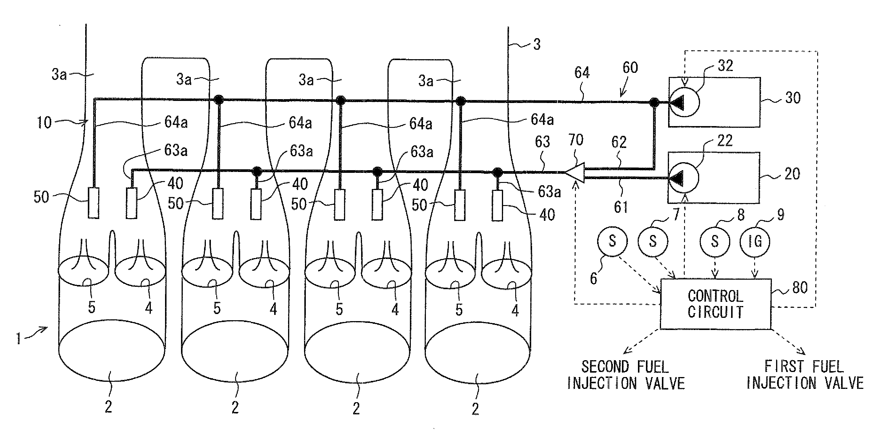
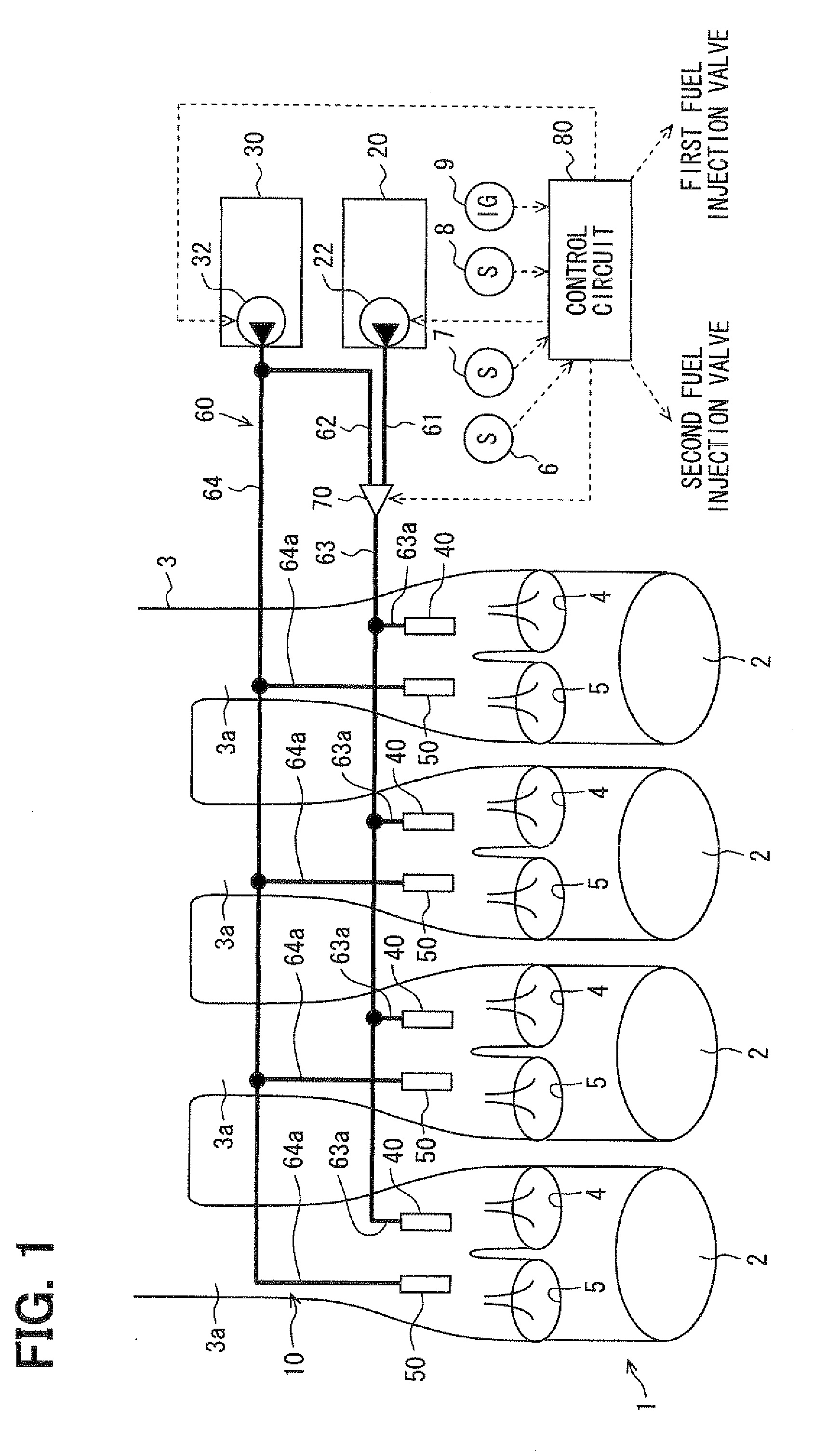
[0024]FIG. 1 shows a fuel supply system 10 according to the first embodiment. The fuel supply system 10 is applied to an internal combustion engine 1 for a flexible fuel vehicle (FFV). The internal combustion engine 1 includes multiple cylinders 2 each being connected with a branch pipe 3a of an air intake manifold 3 via a pair of intake ports 4, 5. In the present structure, air is drawn from the outside of the vehicle through the air intake manifold 3 into each cylinder 2 of the internal combustion engine 1, and fuel spray is supplied into each cylinder through the intake ports 4, 5. The air and the fuel spray are mixed in each cylinder so as to produce air-fuel mixture. The air-fuel mixture is burned in response to spark caused by a spark plug (not shown), thereby causing driving force. The driving force is transmitted to driving wheels of the vehicle.

[0025]The fuel supply system 10 for the internal combustion engine 1 includes fuel tanks 20, 30, fuel pumps 22, 32, fuel injection ...

second embodiment

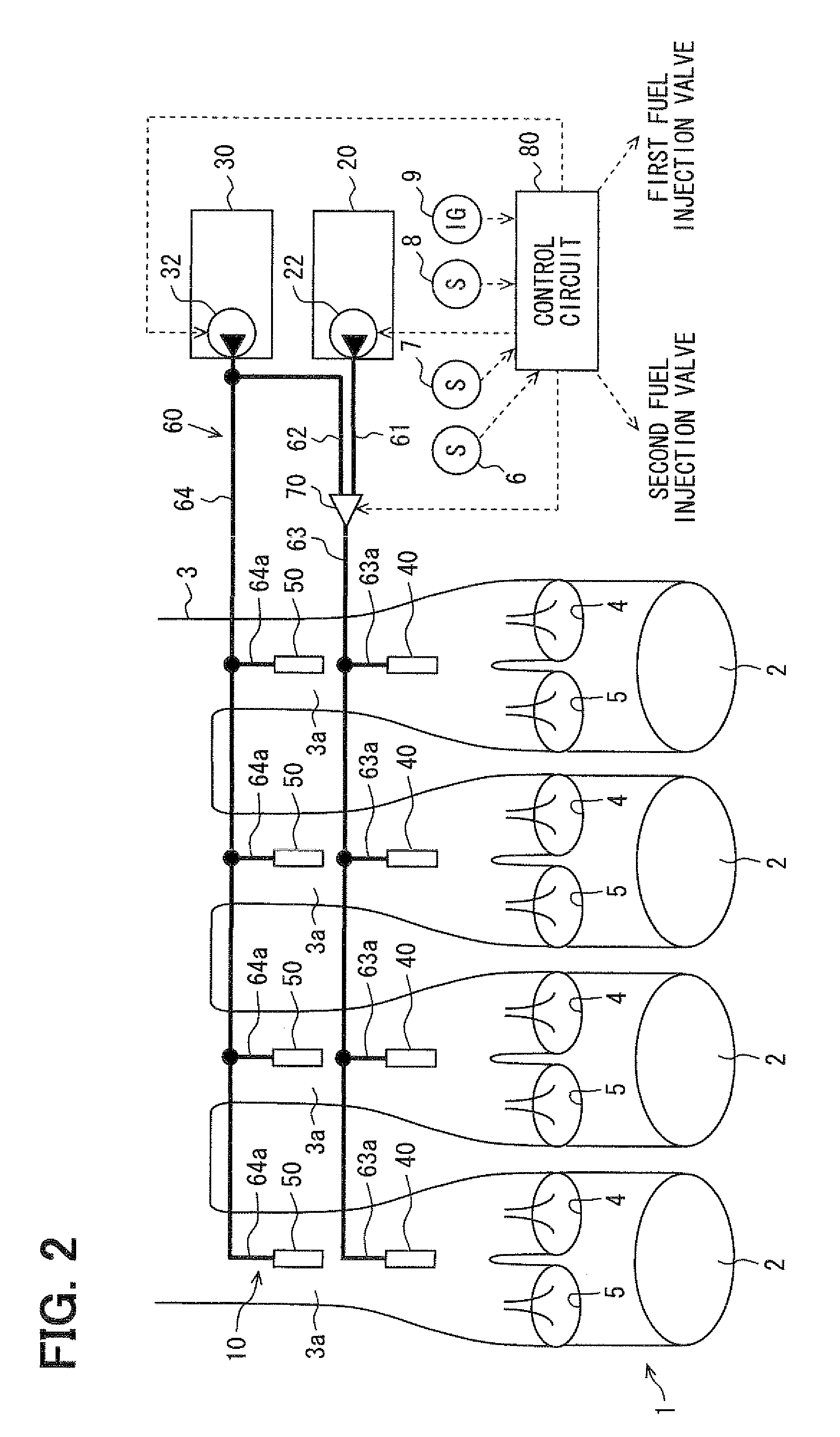
[0045]As shown in FIG. 5, the second embodiment is a modification of the first embodiment. In a fuel supply system 200 of the second embodiment, a pair of the first fuel injection valves 40 is provided to each cylinder 2 of the internal combustion engine 1. In each cylinder 2, one of the pair of first fuel injection valves 40 injects fuel through one intake port 4, and the other of the pair of first fuel injection valves 40 injects fuel through another intake port 5. In the present embodiment, the second fuel injection valve 50 is provided to each cylinder 2 to inject fuel through both the intake ports 4, 5 of the cylinder 2.

[0046]According to the present second embodiment, the pair of first fuel injection valves 40 is capable of injecting a large amount of main-fuel or sub-fuel, which is in appropriate alcohol concentration, into each cylinder 2, in accordance with the operation of the internal combustion engine 1. Therefore, reduction in environmental pollution caused by injection...

third embodiment

[0048]As shown in FIG. 6, the third embodiment is a modification of the first embodiment. In the present third embodiment, a fuel inlet portion 360 of a fuel supply system 300 is not provided with the fuel rails 61, 62, and the first fuel rail 63 is connected with the main-fuel pump 22 in the main-fuel tank 20 to supply main-fuel. The fuel inlet portion 360 is not provided with the common selector valve 70, and each of the branching rails 63a, 64a of the first fuel rail 63 and the second fuel rail 64 and each first fuel injection valve 40 are correspondingly connected with each discrete selector valve 370. Each discrete selector valve 370 is a three-way solenoid valve electrically connected with the control circuit 80. The discrete selector valve 370 is configured to select one of the first fuel rail 63 and the second fuel rail 64 to be connected with the first fuel injection valve 40 in response to electricity supply. When the discrete selector valve 370 communicates the first fuel...


PUM


Abstract

A fuel supply system supplies composite fuel containing alcohol and gasoline to multiple cylinders of an internal combustion engine. The composite fuel includes main-fuel and sub-fuel. The sub-fuel is lower than main-fuel in concentration of alcohol. Each of multiple first fuel injection valves is provided to each of the cylinders for injecting fuel. Each of multiple second fuel injection valves is provided to each of the cylinders for injecting fuel. A fuel inlet portion supplies at least sub-fuel to each of the first fuel injection valves and each of the second fuel injection valves. A selector control unit selects one of main-fuel and sub-fuel supplied through the fuel inlet portion to each of the first fuel injection valves.

Description

CROSS REFERENCE TO RELATED APPLICATIONS[0001]This application is based on and incorporates herein by reference Japanese Patent Application No. 2008-84524 filed on Mar. 27, 2008.FIELD OF THE INVENTION[0002]The present invention relates to a fuel supply system configured to supply and inject composite fuel containing alcohol and gasoline into multiple cylinders of an internal combustion engine. The present invention further relates to a method for supplying the composite fuel.BACKGROUND OF THE INVENTION[0003]In recent years, composite fuel, which is mixture of gasoline and alcohol such as bioethanol, is widely recognized as fuel excellent in reduction in environmental pollution when used for an internal combustion engine. For example, JP-A-2007-278121 proposes a fuel supply system for selectively supplying composite fuel including main-fuel, which is high in alcohol concentration, and sub-fuel, which is low in alcohol concentration, into each cylinder of an internal combustion engine....

Claims


Application Information

Patent Timeline
Patent Type & Authority Applications(United States)
IPC IPC(8): F02D41/30
CPCF02D29/02F02D41/0025F02D41/064F02D41/3094F02D2041/3881F02M43/00F02D19/084F02M63/029Y02T10/36F02D19/0665F02D19/0676F02D19/0692F02D19/081F02M45/00Y02T10/30
Inventor ICHIHARA, HIDEAKIYAMASHITA, YOSHINORISUGIYAMA, KOUICHIOOMURA, HIDEKAZU
Owner DENSO CORP
Why Eureka
Try Eureka