Time acquisition apparatus and radio wave clock

a time acquisition apparatus and radio wave clock technology, applied in the field of time acquisition apparatus and radio wave clock, can solve the problems of many errors in the acquisition of tco data

Active Publication Date: 2009-10-01
CASIO COMPUTER CO LTD
View PDF2 Cites 29 Cited by
  • Summary
  • Abstract
  • Description
  • Claims
  • Application Information

AI Technical Summary

Benefits of technology

[0017]An object of the present invention is to provide a time acquisition apparatus capable of properly obtaining a code included in standard time radio wave to acquire current time without being influenced by a status of electric filed intensity or noise in a signal, and to provide a radio wave clock provided with the time acquisition apparatus.

Problems solved by technology

Under a condition that electric field intensity is weak or that much noise is mixed into the demodulated signal, the acquired TCO data would include many errors.

Method used


Image

  • Time acquisition apparatus and radio wave clock
  • Time acquisition apparatus and radio wave clock
  • Time acquisition apparatus and radio wave clock

Examples


second embodiment

[0096]Next, the present invention will be described.

first embodiment

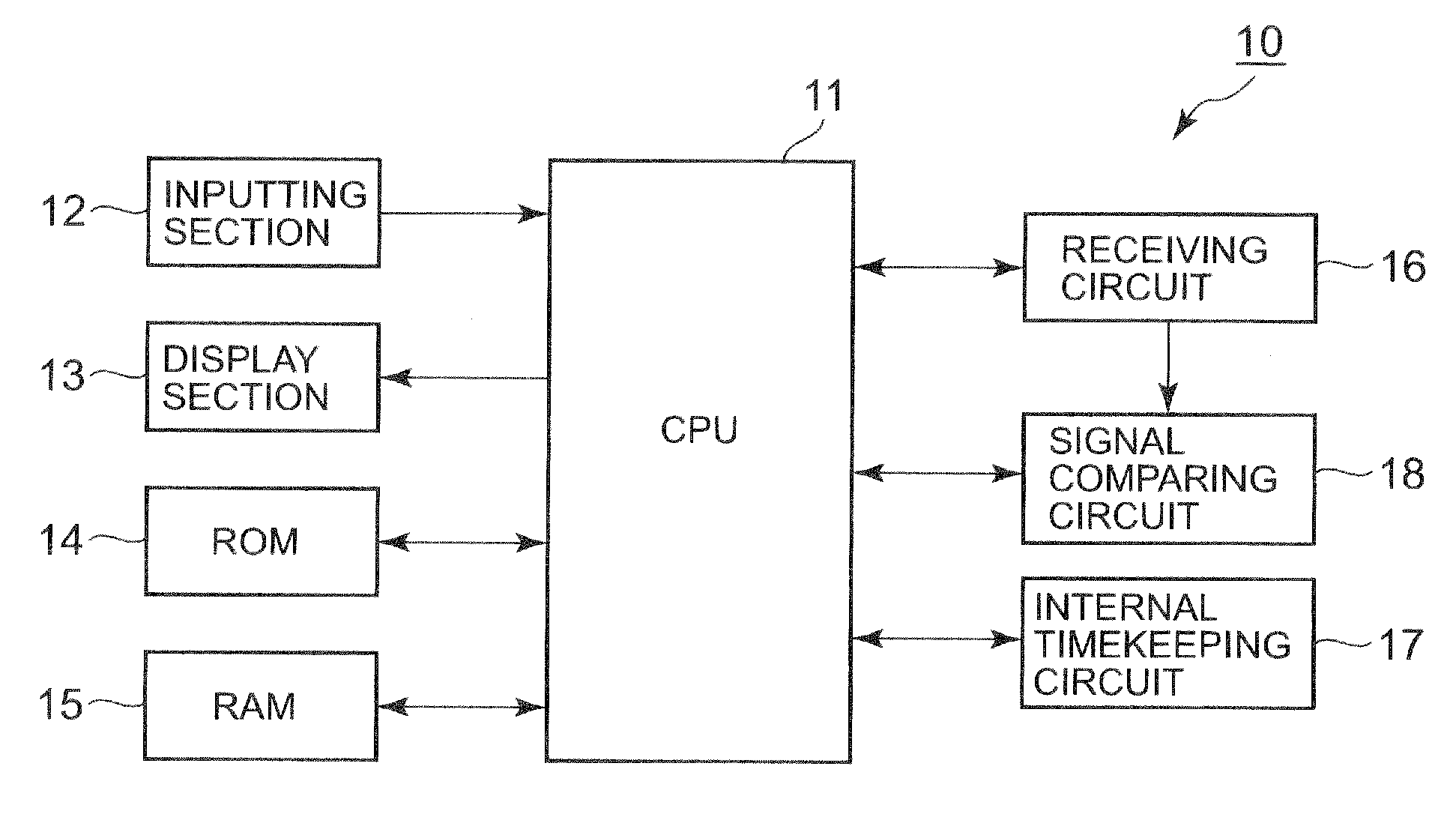
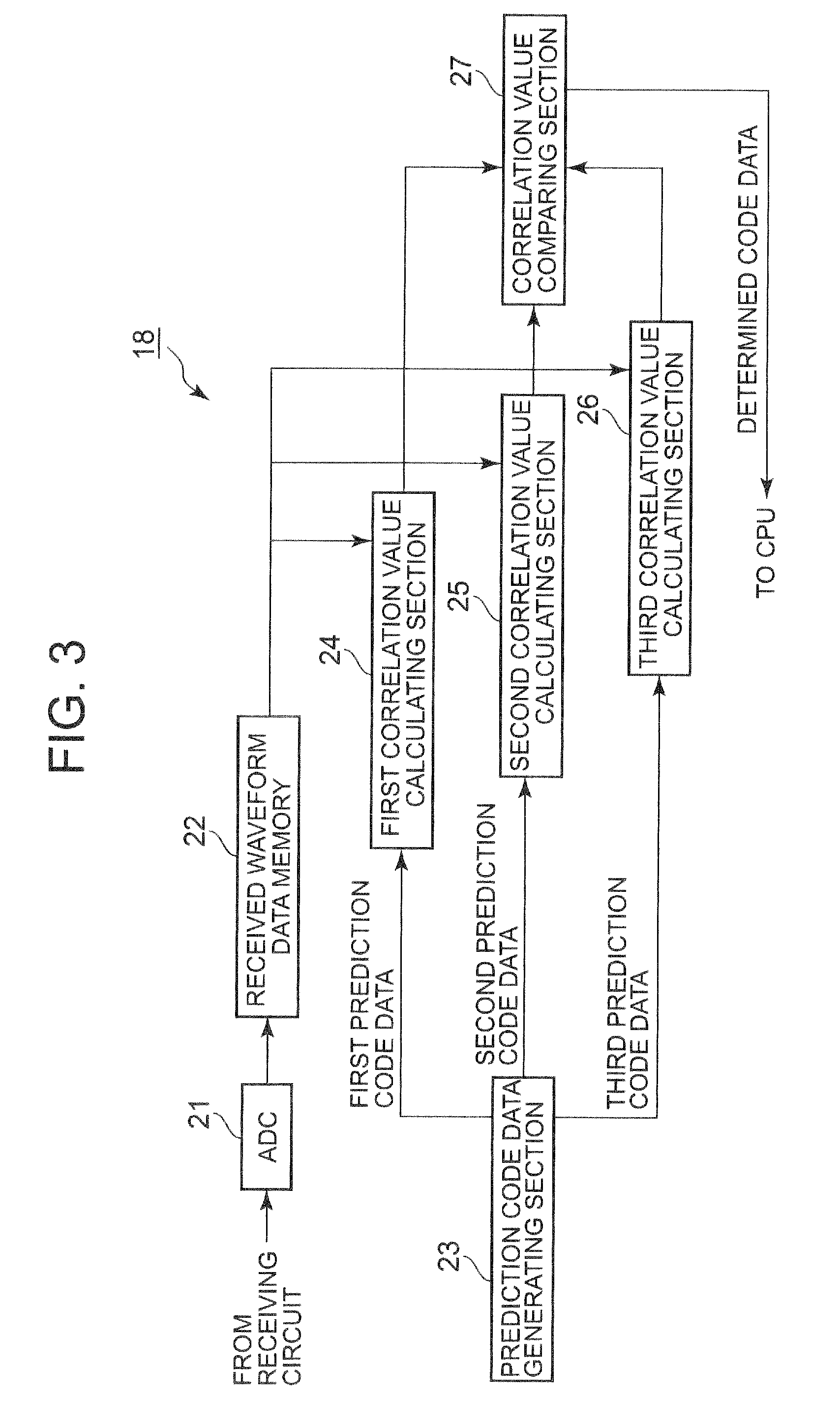
[0097]In the first embodiment, the signal comparing circuit 18 calculates the covariance as the correlation value between the received waveform data and the first prediction code data, the second prediction code data and the third prediction code data respectively, and judges which of the codes the received waveform data corresponds to based on the covariance.

[0098]In the second embodiment, as the correlation value, a residual error which is the sum of absolute values of the differences is calculated, and the code corresponding to the predicted waveform data by which the residual error becomes minimum is specified.

[0099]FIG. 10 is a block diagram showing details of the correlation value calculating section according to the second embodiment. Similar to the case of the first embodiment, though only the first correlation value calculating section 24 will be explained with reference to FIG. 10, the second correlation value calculating section 25 and the third correlation value calculat...

third embodiment

[0107]Next, the present invention will be described.

[0108]In the third embodiment, a cross-correlation function is obtained instead of the covariance (the first embodiment) or the residual error (the second embodiment) FIG. 11 is a block diagram showing details of the correlation value calculating section according to the third embodiment. Similar to the first embodiment and the second embodiment, though only the first correlation value calculating section 24 will be explained with reference to FIG. 11, the second first correlation value calculating section 25 and the third first correlation value calculating section 26 have same configurations as that of the first correlation value calculating section 24.

[0109]As shown in FIG. 11, the first correlation value calculating section 24 includes: an average value calculating section 71 to calculate the average value of the samples of the received waveform data 400; a deviation calculating section 72 to calculate the deviation between eac...


PUM


Abstract

A received waveform memory 22 stores one (1) frame of received waveform data acquired by sampling a signal including a time code with a predetermined sampling period, where each sample is represented by a plurality of bits. Correlation value calculating sections 24-26 compare the received waveform data with one (1) frame of first prediction code data corresponding to a code of a position marker or a marker, where each sample is represented by a plurality of bits, one (1) frame of second prediction code data corresponding to a code “0”, and one (1) frame of third prediction code data corresponding to a code “1” respectively. Correlation value comparing section 27 compares the first, second and third correlation values with one another to specify the prediction code data whose correlation is largest to output the code data.

Description

CROSS-REFERENCE TO RELATED APPLICATIONS[0001]This application is based upon and claims the benefit of priority from the prior Japanese Patent Application No. 2008-95012 filed on Apr. 1, 2008, the entire contents of which are incorporated herein by reference.BACKGROUND OF THE INVENTION[0002]1. Field of the Invention[0003]The present invention relates to a time acquisition apparatus to acquire current time using standard radio wave and a radio wave clock on which the time acquisition apparatus is mounted.[0004]2. Description of Related Art[0005]Currently, a long-wave standard time radio wave is transmitted from transmitting stations in various countries such as Japan, Germany, England and Switzerland For example, in Japan, the standard time radio waves of 40 kHz and 60 kHz that have been subjected to amplitude modulation are respectively transmitted from transmitting stations in Hukushima prefecture and Saga prefecture.[0006]The standard time radio wave includes a code sequence which ...

Claims


Application Information

Patent Timeline
Patent Type & Authority Applications(United States)
IPC IPC(8): G04C11/02G06F15/00G04G5/00G04R20/00G04R20/12
CPCG04R20/10G04G5/002
Inventor ABE, HIDEO
Owner CASIO COMPUTER CO LTD
Why Eureka
Try Eureka