Dereverberation apparatus, dereverberation method, dereverberation program, and recording medium

Active Publication Date: 2009-10-01
NIPPON TELEGRAPH & TELEPHONE CORP
View PDF22 Cites 37 Cited by
  • Summary
  • Abstract
  • Description
  • Claims
  • Application Information

AI Technical Summary

Benefits of technology

[0028]As described above, the present invention can

Problems solved by technology

The superimposed reverberation component strongly degrades the clearness of the acoustic s

Method used


Image

  • Dereverberation apparatus, dereverberation method, dereverberation program, and recording medium
  • Dereverberation apparatus, dereverberation method, dereverberation program, and recording medium
  • Dereverberation apparatus, dereverberation method, dereverberation program, and recording medium

Examples


first embodiment

[0121]A first embodiment of the present invention will be described next. In the first embodiment, the number of sensors M is greater than or equal to 2, i.e., M≧2.

[0122]FIG. 3 is a block diagram showing the hardware structure of a dereverberation apparatus 10 of the first embodiment.

[0123]As shown in FIG. 3, the dereverberation apparatus 10 shown as an example includes a central processing unit (CPU) 11, an input unit 12, an output unit 13, an auxiliary storage device 14, a read-only memory (ROM) 15, a random access memory (RAM) 16, and a bus 17.

[0124]The CPU 11 shown includes a controller 11a, an operation unit 11b, and a register 11c, and performs a variety of operations in accordance with programs read into the register 11c. The input unit 12 is an input interface to which data is input, such as a keyboard or a mouse, and the output unit 13 is an output interface from which data is output. The auxiliary storage device 14 is a hard disk drive, a magneto-optical disc (MO), a semic...

second embodiment

[0165]A second embodiment of the present invention will be described next. The second embodiment is a modification of the first embodiment.

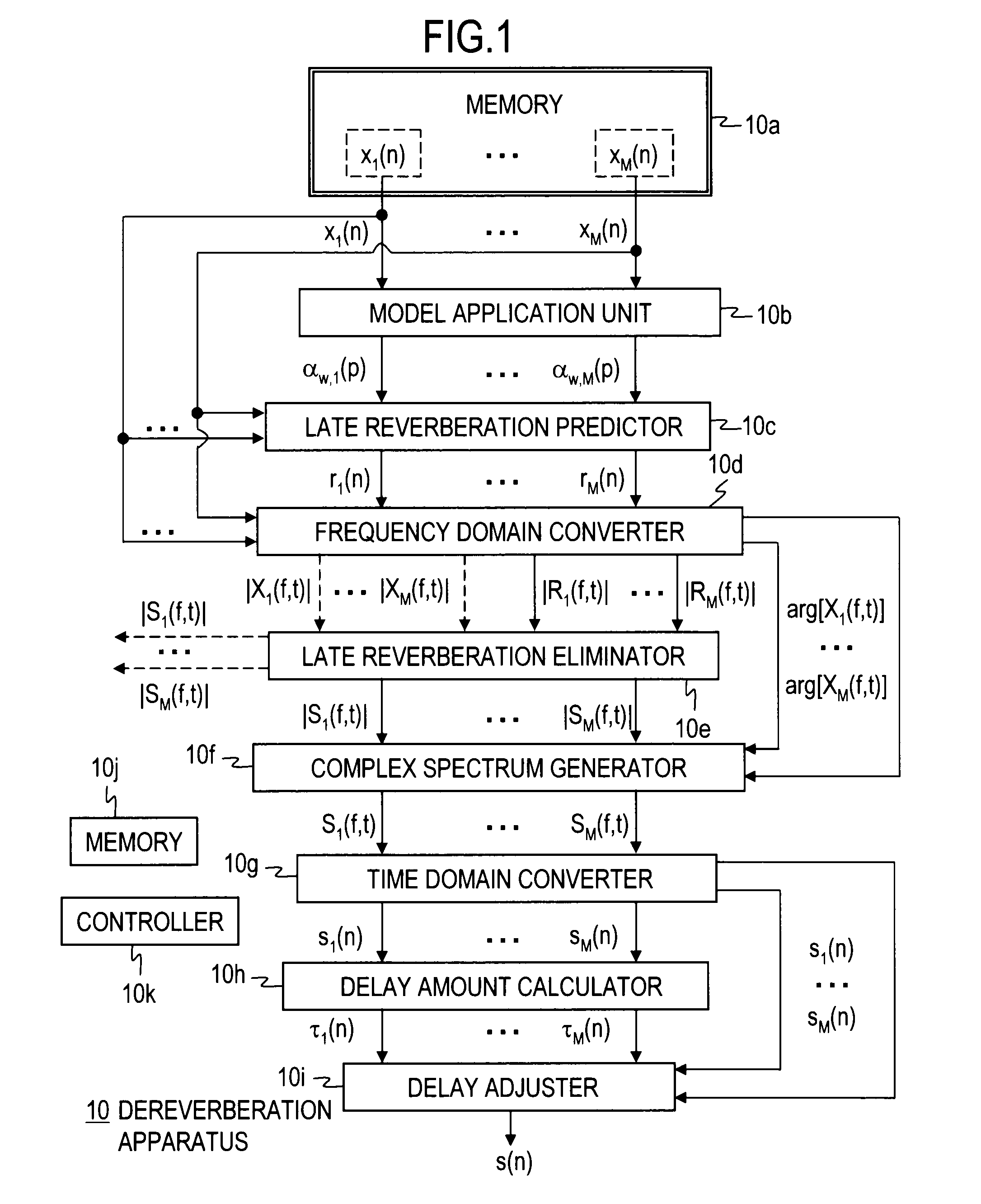
[0166]In the late reverberation prediction process (step 2) of the first embodiment, each linear prediction value obtained by substituting the linear prediction coefficients αw,1(p) to αw,M(p) and the non-pre-whitened discrete acoustic signals x1(n) to xM(n) into the linear prediction term of the multi-step linear prediction model is calculated as each of the predicted late reverberations rw(n) (w=1 to M). In the dereverberation process (step S4), the relative values of the individual sensors, between the amplitude spectra |X1(F, t)| to |XM(f, t)| of the non-pre-whitened discrete acoustic signals in the frequency domain and the amplitude spectra |R1(f, t)| to |RM(f, t)| of the predicted late reverberations in the frequency domain, are obtained, and the relative values are provided as the predicted amplitude spectra |S1(f, t)| to |SM(f, t)| of the...

third embodiment

[0184]A third embodiment of the present invention will be described next. The third embodiment is a modification of the first or second embodiment.

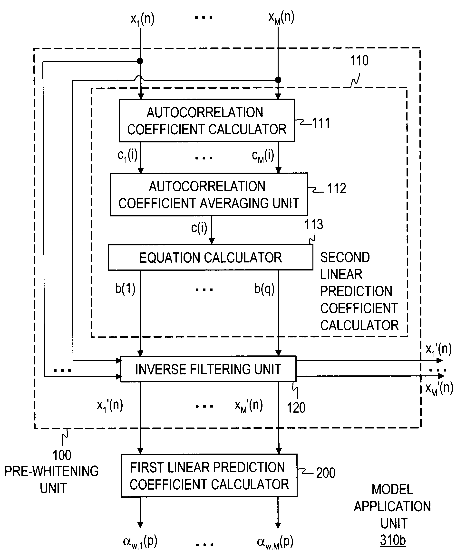
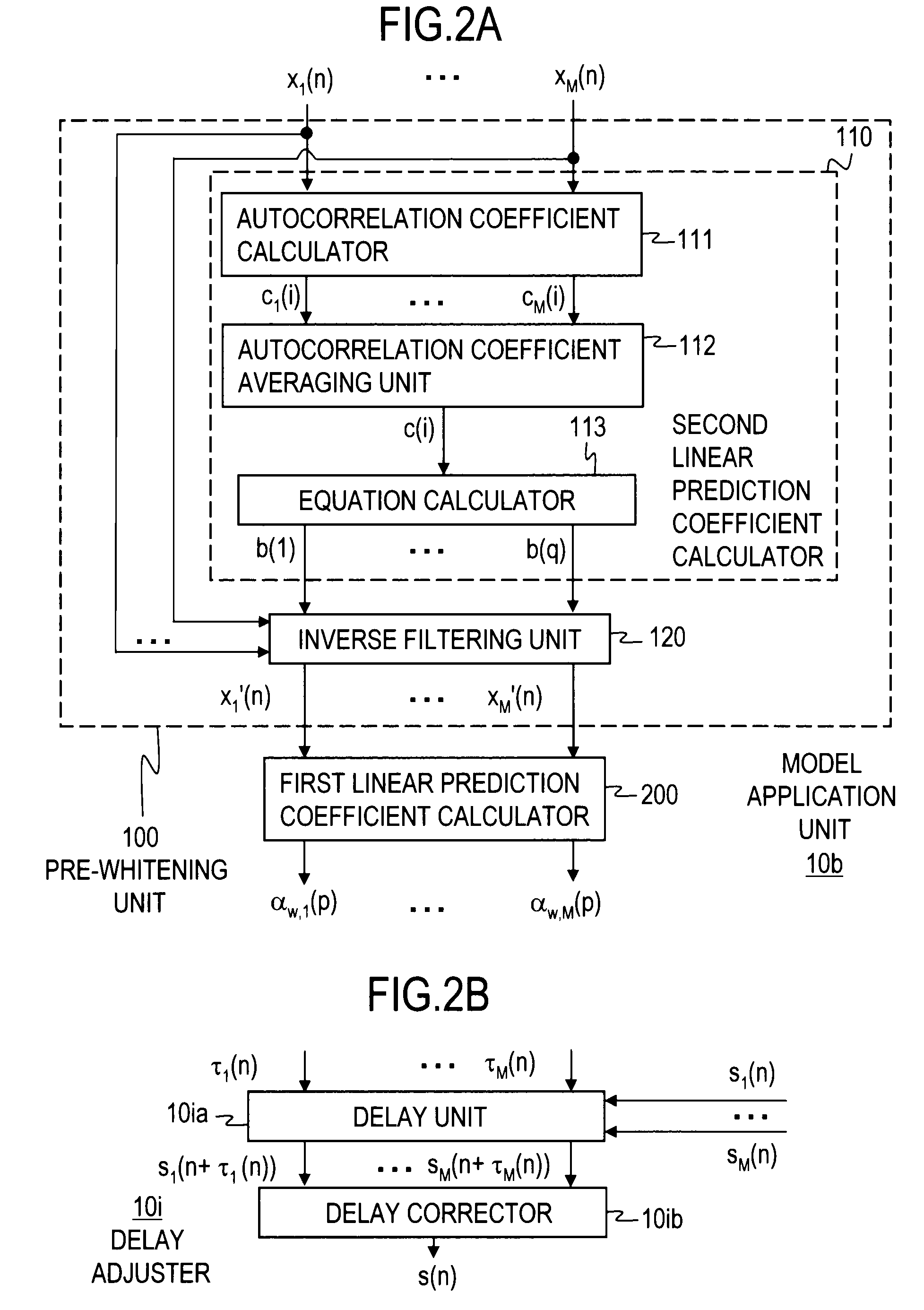
[0185]In the second linear prediction coefficient calculation process (step S31) of the first embodiment, the second linear prediction coefficient calculator 110 calculates the linear prediction coefficients b(1) to b(q) of the short-term linear prediction model, by using the average autocorrelation coefficient c(i) obtained by averaging the autocorrelation coefficients c1(i) to cM(i) generated in the individual channels.

[0186]In a second linear prediction coefficient calculation process (step S31) of the third embodiment, a second linear prediction coefficient calculator 410 calculates the autocorrelation coefficients of discrete acoustic signals obtained by sampling, at multiple points in time, the acoustic signal observed by one sensor that is the closest to the source of the acoustic signal among the M sensors, and calculates the indi...


PUM


Abstract

A model application unit calculates linear prediction coefficients of a multi-step linear prediction model by using discrete acoustic signals. Then, a late reverberation predictor calculates linear prediction values obtained by substituting the linear prediction coefficients and the discrete acoustic signals into linear prediction term of the multi-step linear prediction model, as predicted late reverberations. Next, a frequency domain converter converts the discrete acoustic signals to discrete acoustic signals in the frequency domain and also converts the predicted late reverberations to predicted late reverberations in the frequency domain. A late reverberation eliminator calculates relative values between the amplitude spectra of the discrete acoustic signals expressed in the frequency domain and the amplitude spectra of the predicted late reverberations expressed in the frequency domain, and provides the relative values as predicted amplitude spectra of a dereverberation signal.

Description

TECHNICAL FIELD[0001]The present invention relates to the technical field of acoustic signal processing, and more specifically, to a technique for eliminating reverberation from an acoustic signal containing reverberation.BACKGROUND ART[0002]When an acoustic signal is picked up in an environment having reverberation, the original signal is observed with reverberation superimposed thereon. The superimposed reverberation component strongly degrades the clearness of the acoustic signal, making it difficult to extract the original characteristics of the acoustic signal. If an acoustic signal containing reverberation is recognized by an automatic speech recognition (hereinafter called speech recognition) system, for example, the influence of the reverberation significantly lowers the recognition rate of the speech recognition system.[0003]Dereverberation processing is a technique that can eliminate the superimposed reverberation and can restore the original quality of the acoustic signal...

Claims


Application Information

Patent Timeline
IPC IPC(8): G10L19/00G10L21/0208G10L21/0232G10L21/0264
CPCG10L2021/02082H04R3/04H04N7/147H04S7/305
Inventor KINOSHITA, KEISUKENAKATANI, TOMOHIROMIYOSHI, MASATO
Owner NIPPON TELEGRAPH & TELEPHONE CORP
Why Eureka
Try Eureka