Predictive diagnostics system, apparatus, and method for improved reliability

a predictive diagnostic and equipment technology, applied in the direction of testing/monitoring control systems, program control, instruments, etc., can solve the problems of affecting the reliability of the system, the inability to effectively leverage the conventional process sensor technology for real-time monitoring of the state of critical components and auxiliary equipment sub-systems, and the poor visibility of many detectable faults

Inactive Publication Date: 2009-10-01
ADVANCED ENERGY IND INC
View PDF7 Cites 38 Cited by
  • Summary
  • Abstract
  • Description
  • Claims
  • Application Information

AI Technical Summary

Benefits of technology

[0005]Exemplary embodiments of the present invention that are shown in the drawings are summarized below. These and other embodiments are more fully described in the Detailed Description section. It is to be understood, however, that there is no intention to limit the invention to the forms described in this Summary of the Invention or in the Detailed Description. One skilled in the art can recognize that there are numerous modifications, equivalents and alternative constructions that fall within the spirit and scope of the invention as expressed in the claims.
[0006]In one embodiment the invention may be characterized as a system for managing a processing system. The system may include a wear-out module configured to provide a wear-out signal, the wear-out signal indicating a remai

Problems solved by technology

Unfortunately, real-time monitoring of the state of critical components and auxiliary equipment sub-systems is not adequately leveraged using conventional process sensor technologies.
This results in poor visibility of many detectible, component-level faults and in reporting failures only after an event has occurred.
Recognized as an early indicator to

Method used


Image

  • Predictive diagnostics system, apparatus, and method for improved reliability
  • Predictive diagnostics system, apparatus, and method for improved reliability
  • Predictive diagnostics system, apparatus, and method for improved reliability

Examples


Embodiment Construction

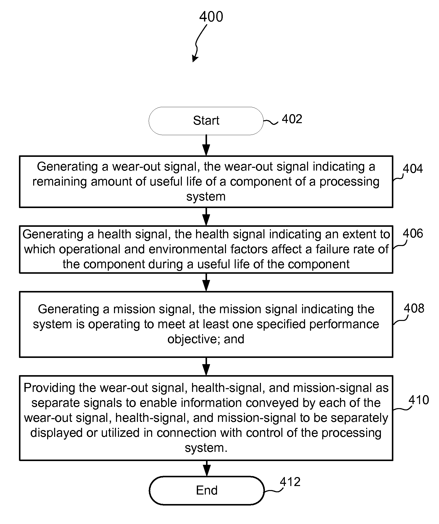
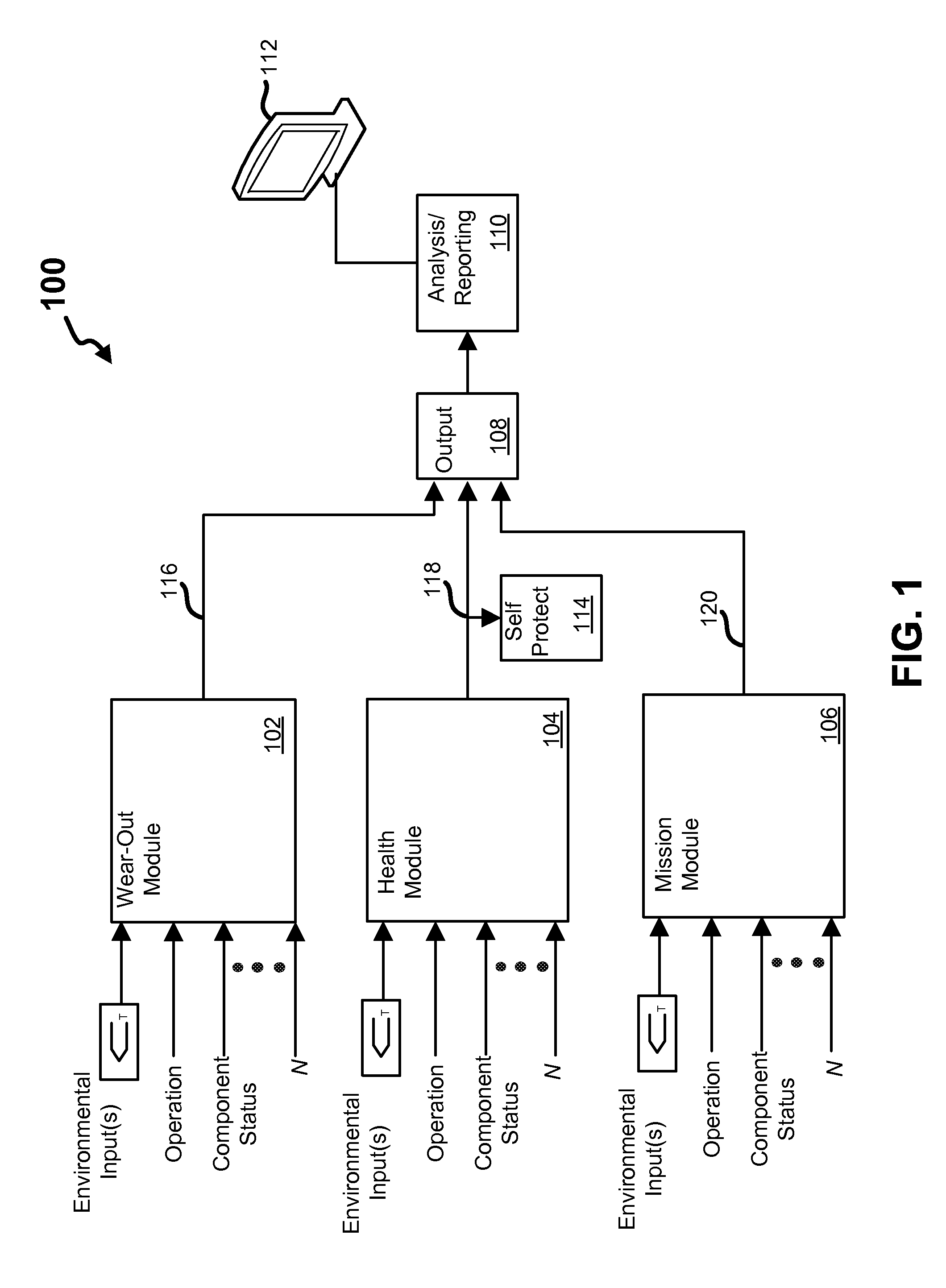
[0015]Referring now to the drawings, where like or similar elements are designated with identical reference numerals throughout the several views, and referring in particular to FIG. 1, it is a block diagram 100 depicting an exemplary system which may be utilized to provide indicators of the operational state, health and performance of a component or sub-system within a processing system.

[0016]As depicted, a wear-out module 102, a health module 104, and a mission module 106 are each coupled to an output module 108, which is coupled to an analysis / reporting module 110. As shown, each of the modules 102, 104, 106 in this embodiment receive N inputs, which may include environmental inputs, operational inputs, and status inputs. As depicted, the analysis / reporting portion 110 is also coupled to a man-machine interface 112, which may include a keyboard, display and pointing device (e.g., a mouse).

[0017]The illustrated arrangement of these modules 102, 104, 106 is logical and not meant to...


PUM


Abstract

A system for managing a processing system and/or a processing system component is described. The system may include a wear-out module configured to provide a wear-out signal, the wear-out signal indicating a remaining amount of useful life of the component; a health module configured to provide a health signal, the health signal indicating an extent to which operational and environmental factors affect a failure rate of the component during a useful life of the component; and a mission module configured to provide a mission signal, the mission signal indicative of whether an operating condition is approaching a threshold that would adversely affect the system's ability to meet at least one performance objective.

Description

FIELD OF THE INVENTION[0001]This invention relates generally to apparatus and methods for analyzing conditions of processing systems, and more particularly to apparatus and methods for predictive diagnostics in plasma processing or power conversion systems.BACKGROUND OF THE INVENTION[0002]Advanced equipment control (AEC) and advanced process control (APC) systems have become commonplace in modern day semiconductor fabrication lines and other advanced manufacturing facilities, providing feedback and feedforward control for enhanced processes as well as detecting faults in hardware and in critical process steps. Unfortunately, real-time monitoring of the state of critical components and auxiliary equipment sub-systems is not adequately leveraged using conventional process sensor technologies. This results in poor visibility of many detectible, component-level faults and in reporting failures only after an event has occurred.[0003]One type of critical auxiliary equipment sub-system uti...

Claims


Application Information

Patent Timeline
IPC IPC(8): G06F11/30
CPCG05B23/0283G05B2219/32234G06F11/008G05B2219/45031G05B2219/37252
Inventor HECKMAN, RANDY L.CARTER, DANIEL C.BROUK, VICTOR L.
Owner ADVANCED ENERGY IND INC
Why Eureka
Try Eureka