
Nozzle cleaner

Active Publication Date: 2009-10-08
KYOKUTOH
View PDF5 Cites 7 Cited by
  • Summary
  • Abstract
  • Description
  • Claims
  • Application Information

AI Technical Summary

Benefits of technology

[0008]An object of the present invention is to provide a nozzle cleaner having a simple and convenient configuration capable of easily achieving the centering of a cutter thereof with respect to a welding nozzle.
[0029]In the nozzle cleaner of the present invention, the start-portion-side cutting blade can prevent an excessive movement of the welding nozzle in an insertion direction because the start-portion-side cutting blade functions a stopper to regulate a movement of the welding nozzle in the insertion direction. Accordingly, it is possible to accurately position the welding nozzle at the sputter removing position. In the nozzle cleaner having the above-described configuration, it is possible not only to remove sputter attached to the inner peripheral surface of the welding nozzle by the inner-periphery-side cutting blade, but also to remove sputter attached to the tip surface of the welding nozzle by the start-portion-side cutting blade.

Problems solved by technology

In this case, there is another problem in that it is difficult to move the cutter while precisely centering the cutter with respect to the welding nozzle.

Method used


Image

  • Nozzle cleaner
  • Nozzle cleaner
  • Nozzle cleaner

Examples


Embodiment Construction

[0045]Reference will now be made in detail to the preferred embodiments of the present invention, examples of which are illustrated in the accompanying drawings. Wherever possible, the same reference numbers will be used throughout the drawings to refer to the same or like parts.

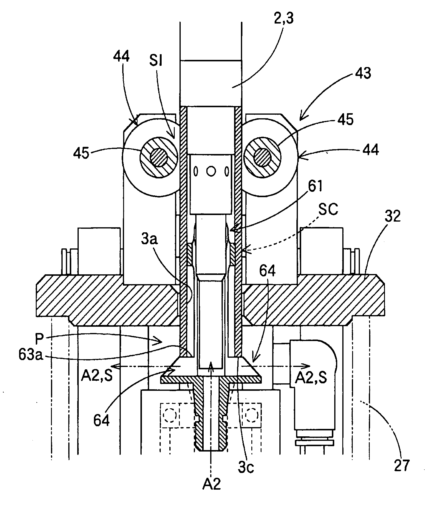
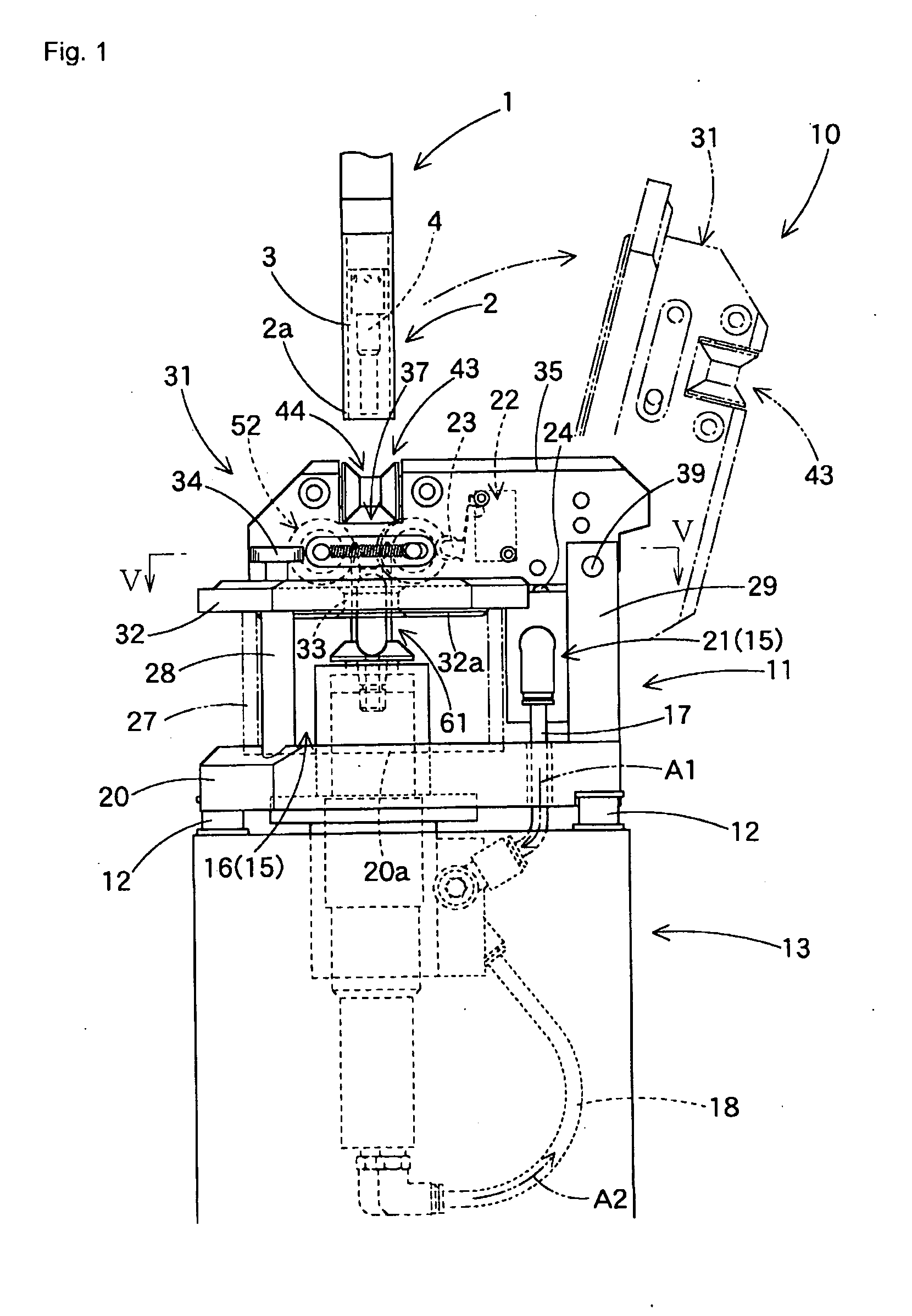
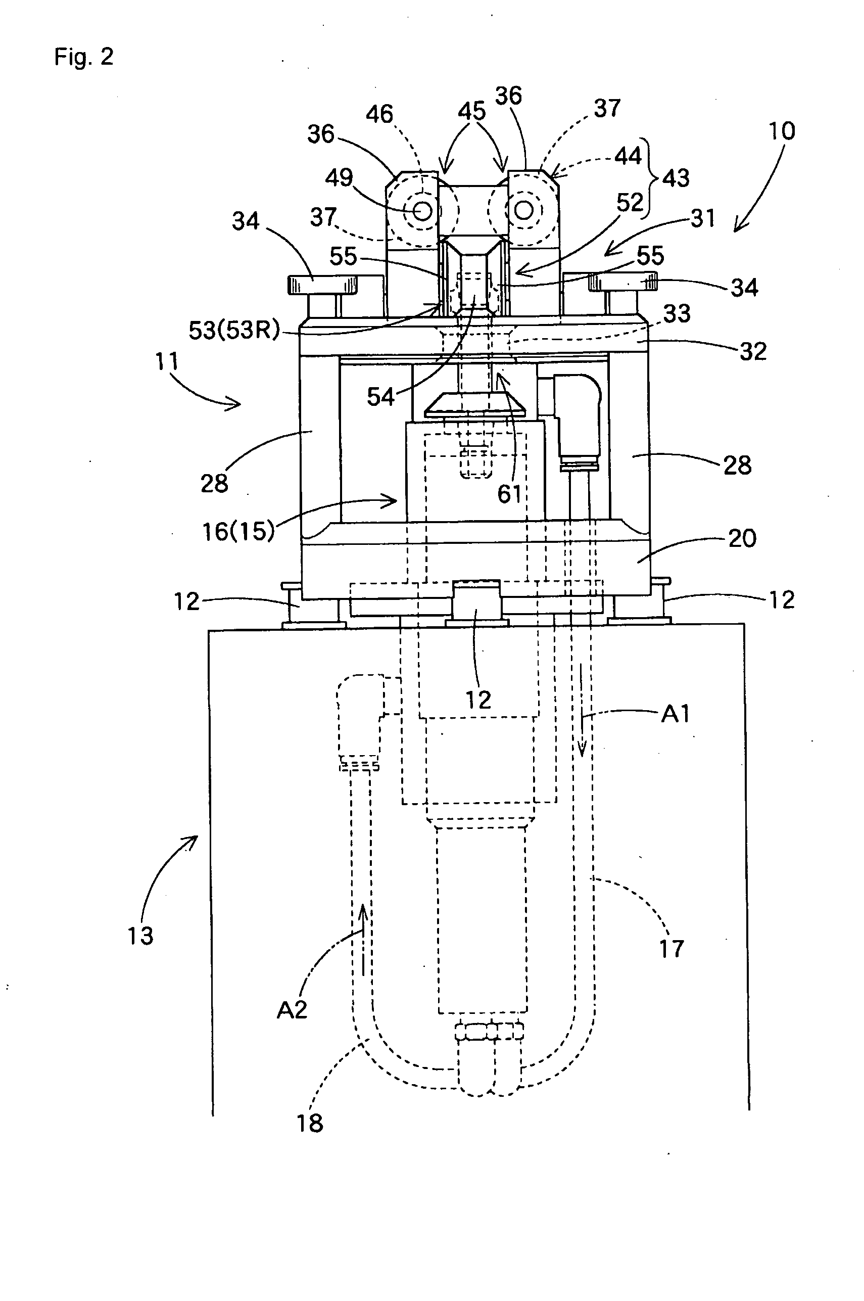
[0046]Referring to FIGS. 1 to 3, a nozzle cleaner 10 according to an exemplary embodiment of the present invention is illustrated. The nozzle cleaner 10 includes a cleaner body 11, and a support frame 13 to support the cleaner body 11. The cleaner body 11 is connected to the support frame 13 via dampers 12 respectively arranged at several regions (for example, three regions) on an outer periphery of the cleaner body 11, in order to absorb a horizontal position deviation (in order to allow the cleaner body 11 to move horizontally) (FIGS. 1 and 2). In the illustrated embodiment, the support frame 13 is implemented by a motor housing. In this case, the support frame 13 covers a driving mechanism 15. Also, in th...


PUM

PropertyMeasurementUnit
Diameteraaaaaaaaaa

Abstract

A nozzle cleaner having a configuration for centering a cutter thereof with respect to a welding nozzle. The nozzle cleaner peels off sputter from an inner peripheral surface of a welding nozzle by inserting the cutter toward the inner peripheral surface of the welding nozzle, and then rotating the cutter. The nozzle cleaner includes a guide mechanism to center the welding nozzle with respect to the cutter. The guide mechanism includes an insertion-side roller unit and a cutter-side roller unit, each having a pair of guide rollers having a smaller diameter portion and a pair of enlarged diameter portions. The enlarged diameter portions guide the welding nozzle to the vicinity of the central position of the corresponding smaller diameter portion. The facing guide rollers of the cutter-side roller unit and of the insertion-side roller unit are arranged in arrangement directions orthogonal to each other, respectively.

Description

[0001]This application claims the benefit of Japanese Patent Application No. 2008-100547, filed on Apr. 8, 2008 which is hereby incorporated by reference as if fully set forth herein.BACKGROUND OF THE INVENTION[0002]1. Field of the Invention[0003]The present invention relates to a nozzle cleaner for removing sputter attached to a cylindrical welding nozzle used in a gas arc welding process.[0004]2. Discussion of the Related Art[0005]Conventionally, a nozzle cleaner is used to remove sputter attached to a cylindrical welding nozzle used in a gas arc welding process. There is a conventional nozzle cleaner including a cutter. In this nozzle cleaner, a blade of the cutter is inserted into a welding nozzle retained by a retainer such that the blade comes into contact with an inner peripheral surface of the welding nozzle. As the cutter rotates, the blade of the cutter peels off sputter from the inner peripheral surface of the welding nozzle, thereby removing the sputter. Such a conventio...

Claims


Application Information

Patent Timeline
IPC IPC(8): B08B9/045B23K9/32B08B9/047
CPCB23K9/328B23K9/32B23K9/29B23K9/28
Inventor NAKAZIMA, KOTARO
Owner KYOKUTOH
Learn More